
slot drilling machine

A drilling machine and slotting technology, which is applied in the direction of rotary drilling, percussion drilling, rotary drilling rigs, etc., can solve the problems of high requirements, inability to meet the special requirements of N00 construction method, and inability to realize flexibly, etc. To achieve the effect of precise drilling positioning

Active Publication Date: 2020-11-10
CHINA UNIV OF MINING & TECH (BEIJING)
View PDF8 Cites 0 Cited by
  • Summary
  • Abstract
  • Description
  • Claims
  • Application Information

AI Technical Summary

Problems solved by technology

Since the N00 construction method is a new coal mining process, according to the requirements of the construction method, firstly adjust the drilling rig in place, including the adjustment of the front, rear, left and right distances between the drill arm and the predetermined working position of the roof, as well as the adjustment of the drill arm and the roof. The angle adjustment of the predetermined working position, etc. Therefore, it has higher requirements for directional slit construction equipment, which must have the characteristics of flexible operation, fast and accurate positioning, and high drilling efficiency. However, some directional drilling in the prior art Although the equipment can easily adjust the front, back, left and right distances between the drill arm and the predetermined working position of the roof, it cannot be flexibly adjusted for the angle between the drill arm and the predetermined working position of the roof. Therefore, it cannot meet the special construction requirements of N00 construction method

Method used


Image

  • slot drilling machine
  • slot drilling machine
  • slot drilling machine

Examples


Embodiment Construction

[0046] Example embodiments will now be described more fully with reference to the accompanying drawings. Example embodiments may, however, be embodied in many forms and should not be construed as limited to the embodiments set forth herein; rather, these embodiments are provided so that this disclosure will be thorough and complete, and will fully convey the concept of example embodiments to those skilled in the art. The same reference numerals in the drawings denote the same or similar structures, and thus their detailed descriptions will be omitted.

[0047] Furthermore, the described features, structures, or characteristics may be combined in any suitable manner in one or more embodiments. In the following description, numerous specific details are provided in order to give a thorough understanding of embodiments of the invention. However, one skilled in the art will appreciate that the technical solutions of the present invention may be practiced without one or more of t...


PUM


Abstract

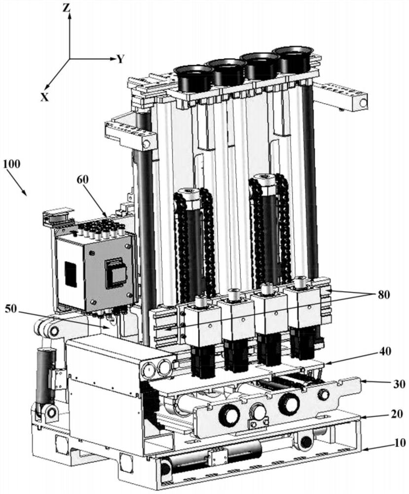
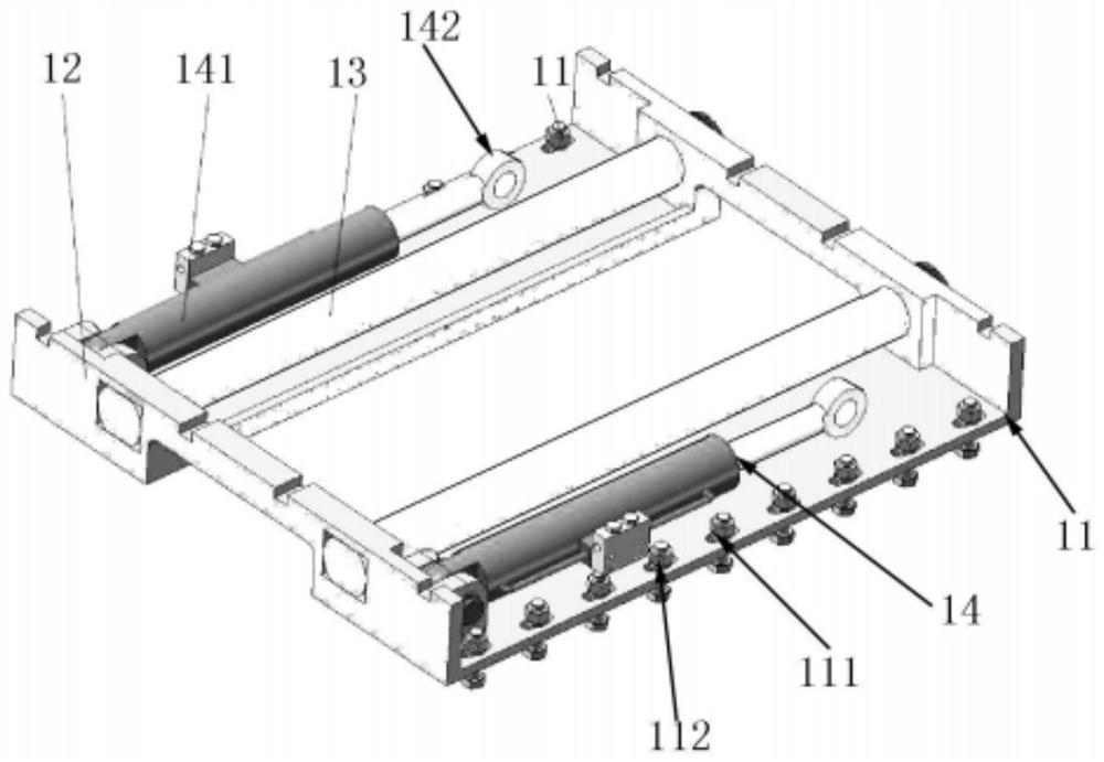
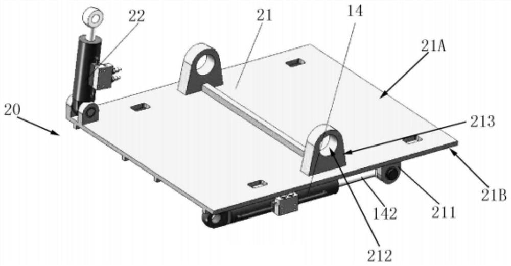
The invention relates to a joint-cutting hole drilling machine. The joint-cutting hole drilling machine is fixed to a hydraulic support, the hydraulic support is used for positioning and constructionof hole drilling. The joint-cutting hole drilling machine includes an installation base which is connected with the hydraulic support, a front-rear sliding seat which is installed on the installationbase and can be driven to move back and forth relative to the installation base, a front-rear swinging seat which is installed on the front-rear sliding seat and can be driven to swing back and forthrelative to the front-rear sliding seat, a left-right sliding seat which is installed on the front-rear swinging seat and can be driven to slide left and right relative to the front-rear swinging seat, a reversing seat which is installed on the left-right sliding seat and can be driven to deflect relative to the left-right sliding seat, and a left-right swinging seat which is installed on the reversing seat and can be driven to swing left and right relative to the reversing seat. One or more drill booms are installed on the left-right swinging seat, the drill booms are provided with drill bitsand drill pipes, and the drill pipes are hydraulically driven for hole drilling construction. According to the joint-cutting hole drilling machine, precise adjustment of the drilling direction and angle of the drill booms can be realized, and the construction requirements for an N00 construction method are met.

Description

technical field [0001] The invention relates to rock soil operation equipment technology, in particular to a slotting hole drilling machine for mining. Background technique [0002] The breakthrough research of the N00 method of coal mining is a method of mining without roadway and coal pillars innovatively proposed by Academician He Manchao. "N" working faces are mined. In this method, the propulsion cylinder is installed to ensure the ventilation of the entire coal mining area, and when the mining of each working face in the panel area is carried out, a part of the goaf is used to implement roof cutting and pressure relief for automatic roadway formation, and no further excavation is required. It is no longer necessary to set coal pillars in the tunnel roadway, so as to save resources and improve efficiency. For related technologies of N00 construction method, please refer to CNA105240013A. One of the characteristics of the N00 construction method is that during the mini...

Claims


Application Information

Patent Timeline
Patent Type & Authority Patents(China)
IPC IPC(8): E21B15/04E21B7/04E21B3/02E21B19/10
CPCE21B3/02E21B7/04E21B15/003E21B15/045E21B19/10
Inventor 何满潮王亚军高玉兵朱珍
Owner CHINA UNIV OF MINING & TECH (BEIJING)
Learn More