
Mud splash-proof valve for oil drilling

An oil drilling and mud technology, which is applied in the field of mud splash valve for oil drilling, can solve the problems of increasing safety hazards, low reliability, affecting operations, etc., to simplify processing and installation processes, increase system performance stability, and increase sealing The effect of reliability

Pending Publication Date: 2019-08-06
东营市创元石油机械制造有限公司
View PDF0 Cites 3 Cited by
  • Summary
  • Abstract
  • Description
  • Claims
  • Application Information

AI Technical Summary

Problems solved by technology

[0002] In oil, natural gas and other drilling and workover operations, in order to prevent the mud in the kelly and its upper pipe string from spraying onto the drill floor when connecting a single root, pollute the environment, affect operations, cause waste, and increase potential safety hazards , and the anti-splash valve is installed at the lower part of the cock valve under the kelly or the kelly. Most of the anti-splash valves currently used have complex structures, poor workmanship, unreasonable valve core structure, fast mud flow rate and serious erosion, and high processing and use costs. , the hard-to-hard sealing structure has unreliable sealing performance under low pressure, and when it is stuck, the resistance is large and affects normal drilling operations. The failure rate is high, the reliability is low, and the service life is short, threatening the safety of relevant personnel and facilities.

Method used


Image

  • Mud splash-proof valve for oil drilling

Examples


Embodiment 1

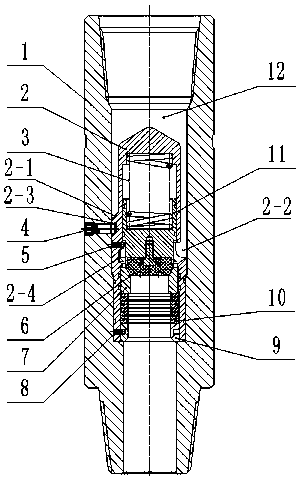
[0017] The mud splash prevention valve for oil drilling includes a shell 1, a valve core body 2, a spring 3, a valve seat 7, a strong spring 10, a piston 11, a "Jie"-shaped vertical rib 2-1, and a "Twenty"-shaped flow channel 2-2 , fixed groove 2-3, "boat" shaped deceleration groove 2-4, fixed screw 4, limit pin 5, valve core 6, support pin 8, support seat 9, mud channel 12, except shell 1, fixed screw 4 The other accessories outside form the integral valve core, in which the shell 1 is in the shape of a round tube, the integral valve core is supported on the second step of the inner hole, and the valve core body 2 is in the shape of a barrel with an open lower end. There are two annular grooves on the upward barrel wall of the first step. There are seals in the grooves, and the valve seat 7 is installed in close fit. The spring 3 is supported by the bottom of the barrel. Rib 2-1 and three "Twenty" shaped runners 2-2 connected with the inside of the barrel, three 120° evenly d...

Embodiment 2

[0024] What is different from the above example is that the strong spring 10 is a group of cylindrical helical composite springs with rectangular cross section.

[0025] The spool 6 has an integral structure and is processed by polyether ether ketone.

[0026] The material of the valve seat 7 is ceramics.

Embodiment 3

[0028] The difference from the above two examples is that the valve core 6 is a monolithic structure, which is processed from a composite material composed of polytetrafluoroethylene, molybdenum disulfide, copper powder and the like.

[0029] The material of valve seat 7 is high chromium alloy.


PUM


Abstract

The invention discloses a mud splash-proof valve for oil drilling. A shell is in a circular pipe shape, and an overall valve element is supported on a second step of an inner hole; a valve element body is in a cylinder shape with the lower end open, four steps are sequentially machined in a cylinder from bottom to top, and a valve seat is mounted on the upward cylinder wall of the first step in anattached mode; and during pump starting, mud enters the upper inner hole of the shell from an upper drilling tool, and enters a deceleration groove shaped like the Chinese character 'chuan' through three flow channels shaped like the Chinese character 'nian' to form an even and stable mud flow to enter the cylinder of the valve element body, and thus the valve element ascends to the upper parts of the flow channels shaped like the Chinese character 'nian' and an opening in the cylinder along with a piston. A soft-to-hard sealing pair is formed between the valve element and the valve seat, thus the sealing reliability is improved, the valve seat is supported through a supporting pin, a supporting seat and a strong spring, machining and mounting processes are simplified, and the product cost is lowered.

Description

technical field [0001] The invention relates to the technical field of an anti-splash valve for drilling in petroleum industry—a mud anti-splash valve, in particular to a mud anti-splash valve for oil drilling. Background technique [0002] In oil, natural gas and other drilling and workover operations, in order to prevent the mud in the kelly and its upper pipe string from spraying onto the drill floor when connecting a single root, pollute the environment, affect operations, cause waste, and increase potential safety hazards , and the anti-splash valve is installed at the lower part of the cock valve under the kelly or the kelly. Most of the anti-splash valves currently used have complex structures, poor workmanship, unreasonable valve core structure, fast mud flow rate and serious erosion, and high processing and use costs. , The hard-to-hard sealing structure has unreliable sealing performance under low pressure. When stuck, the resistance is large and normal drilling op...

Claims


Application Information

Patent Timeline
IPC IPC(8): E21B21/10
CPCE21B21/10
Inventor 朱怀军田相录蒙毅王笑笑陈欢欢
Owner 东营市创元石油机械制造有限公司
Learn More