Workpiece table device and immersive lithographic device

A technology of workpiece table and edge position, which is applied in the field of lithography machine and can solve problems such as thermal deformation of workpieces

Inactive Publication Date: 2019-08-06
SHANGHAI MICRO ELECTRONICS EQUIP (GRP) CO LTD
View PDF5 Cites 1 Cited by
  • Summary
  • Abstract
  • Description
  • Claims
  • Application Information

AI Technical Summary

Problems solved by technology

[0015] The purpose of the present invention is to provide a workpiece table device and immersion lithography equipment to solve the problem o

Method used


Image

  • Workpiece table device and immersive lithographic device
  • Workpiece table device and immersive lithographic device
  • Workpiece table device and immersive lithographic device

Examples


Embodiment 1

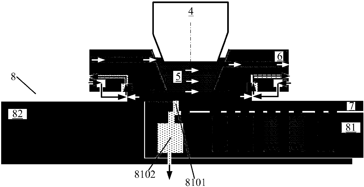
[0048] like Figure 4-9 As shown, the present invention provides a workpiece table device, including: a workpiece table unit 8, an edge gas-liquid recovery unit, a heat isolation unit and a heat external introduction unit, and the edge gas-liquid recovery unit is arranged around the workpiece table unit 8, the heat isolation unit is arranged around the inside and / or outside of the edge gas-liquid recovery unit, and the heat external introduction unit is used to extract the energy at the edge gas-liquid recovery unit to The workpiece table unit 8 is outside.

[0049] Wherein, the edge gas-liquid recovery unit is annularly arranged at the edge position in the workpiece table unit, the edge gas-liquid recovery unit includes a gas-liquid recovery cavity 8102, and the workpiece table unit 8 includes a workpiece table body 81 and Work table base 82.

[0050] The heat isolation unit is used to prevent the refrigeration power in the edge gas-liquid recovery unit from “leaking” to ot...

Embodiment 2

[0061] Please refer to Figure 11 and Figure 12 , in this embodiment, the heat diffusion mechanism 8107 is located at the bottom of the workpiece table base 82 . That is to say, the heat diffusion mechanism 8107 can be designed to be close to the workpiece table base 82 , or directly have a certain distance from the workpiece table base 82 , so as to improve the heat dissipation capability and further reduce the temperature influence on the workpiece table base 82 . The heat isolation unit is used to prevent the cooling power in the gas-liquid recovery chamber 8102 from “leaking” into the workpiece table base 82 , which is beneficial to improve the overall temperature uniformity of the wafer table base 82 .

Embodiment 3

[0063] In this embodiment, a heat diffusion mechanism is provided at the bottom of the workpiece table base 82 and the bottom of the workpiece table body 81 at the same time, that is, the heat diffusion mechanism includes a first heat diffusion mechanism arranged at the bottom of the workpiece table body 81 and a first heat diffusion mechanism arranged at the bottom of the workpiece table body 81. The second heat diffusion mechanism at the bottom of the workpiece table base 82 . The first heat diffusion mechanism and the second heat diffusion mechanism may be connected to the heat transfer mechanism 8106 respectively. A connection structure capable of realizing heat transfer may be provided between the first heat diffusion mechanism and the second heat diffusion mechanism, and the connection structure may be a part of the heat transfer mechanism 8106 or an independent structure. Setting the first heat diffusion mechanism and the second heat diffusion mechanism at the same time...


PUM


Abstract

A workpiece table device of the invention comprises a workpiece table unit, an edge gas-liquid recovery unit and a heat isolation unit, wherein the edge gas-liquid recovery unit surrounds an edge position disposed in the workpiece table unit; and the heat isolation unit surrounds the inner side and/or outer side of the edge gas-liquid recovery unit. The invention provides a workpiece table deviceand an immersive lithographic device, which can thermally isolate a refrigeration source at the edge gas-liquid recovery unit from other parts of the workpiece table unit in order to prevent the energy in the edge gas-liquid recovery unit from leaking to other parts in the workpiece table unit and to improve the reliability of the workpiece table unit.

Description

technical field [0001] The invention relates to the field of lithography machines, in particular to a workpiece table device and immersion lithography equipment. Background technique [0002] Modern lithography equipment is based on optical lithography, which uses an optical system to accurately project and expose the pattern on the mask to the substrate (such as: silicon wafer) coated with photoresist. Immersion lithography refers to the filling of immersion liquid (such as water) between the exposure lens and the silicon wafer to replace the corresponding air in the traditional dry lithography technology. Since the refractive index of water is larger than that of air, this increases the numerical aperture of the lens group, thereby obtaining a smaller characteristic linewidth. [0003] A kind of immersion lithography equipment in the prior art such as figure 1 As shown, the main frame 1 supports an illumination system 2, a projection objective lens 4 and a work table 8, ...

Claims


Application Information

Patent Timeline
IPC IPC(8): G03F7/20
CPCG03F7/70341G03F7/70716G03F7/70875G03F7/20
Inventor 赵丹平魏巍罗晋刘伟
Owner SHANGHAI MICRO ELECTRONICS EQUIP (GRP) CO LTD
Why Eureka
Try Eureka