
Gas treatment apparatus and operation method using same

A technology of gas treatment and operation method, applied in waste gas treatment, waste heat treatment, reduction of gas emission, etc., can solve the problems of low gas utilization rate, low temperature, difficult to know and adjust the treatment efficiency of blast furnace charging, etc., and achieve the structure and operation method. The effect of simplifying and improving processing efficiency

Inactive Publication Date: 2019-08-06
POHANG IRON & STEEL CO LTD
View PDF8 Cites 0 Cited by
  • Summary
  • Abstract
  • Description
  • Claims
  • Application Information

AI Technical Summary

Problems solved by technology

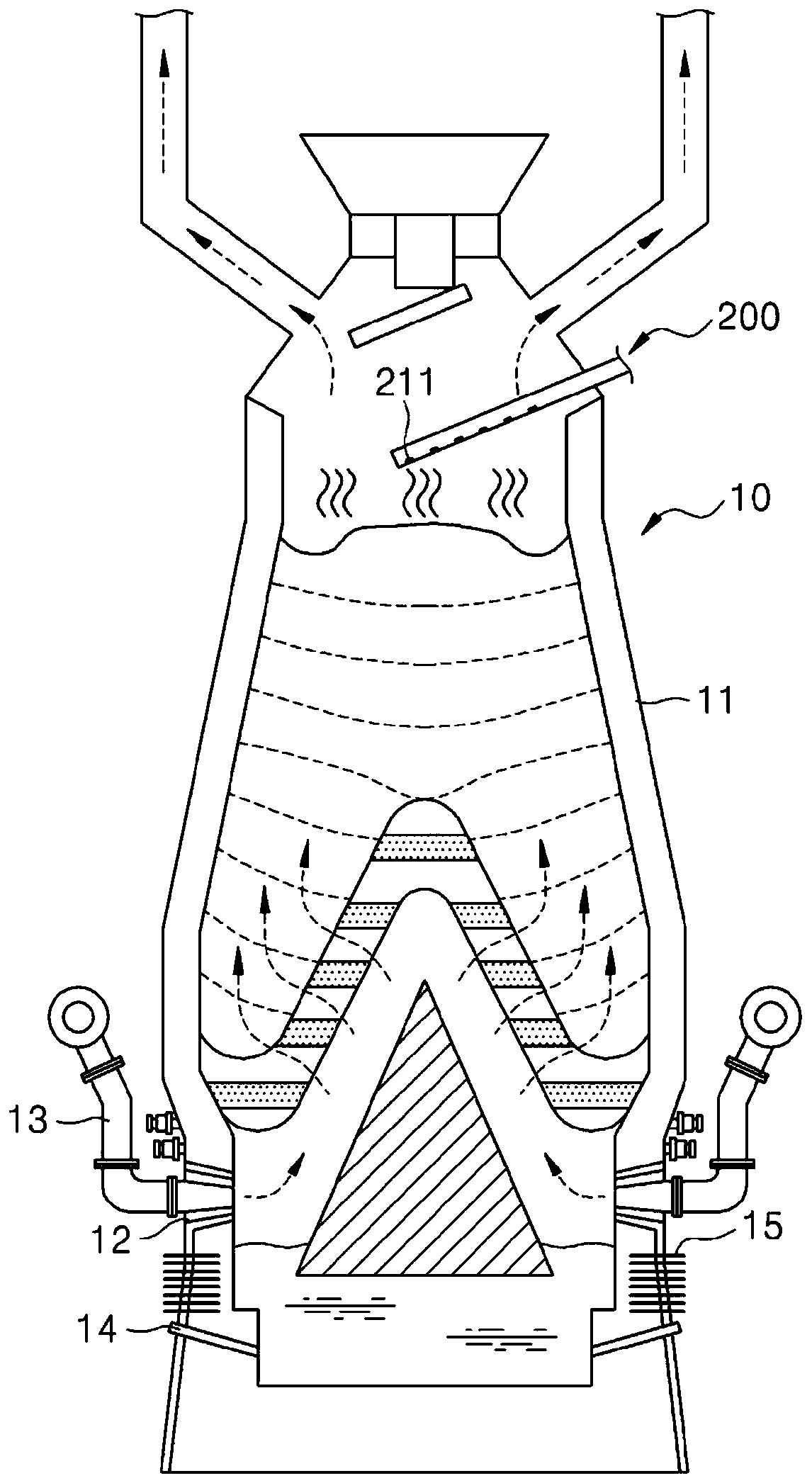
[0010] For example, in the central part of a blast furnace with high permeability, since coke with a large particle size is loaded into the central part, a large amount of gas is discharged from the central part, therefore, the measured temperature is high, but the gas Utilization is low because iron ore is scarce
On the other hand, on the inner wall side of the blast furnace with low permeability, since coke with a small particle size is loaded onto the inner wall side, a small amount of gas is discharged from the inner wall side, therefore, the measured temperature is lower and Gas utilization is also lower
That is, since the temperature distribution does not correspond to the gas utilization rate one-to-one, it is difficult to accurately estimate the gas utilization rate distribution in the blast furnace from the temperature distribution in the blast furnace
Therefore, it is difficult to accurately evaluate the processing efficiency, and it is difficult to know how to adjust the loading state of the blast furnace charge to achieve the optimal processing efficiency

Method used


Image

  • Gas treatment apparatus and operation method using same
  • Gas treatment apparatus and operation method using same
  • Gas treatment apparatus and operation method using same

Examples


Embodiment Construction

[0053] Hereinafter, embodiments of the present disclosure will be described in detail with reference to the accompanying drawings. However, the present disclosure is not limited to the embodiments disclosed below, but may be implemented in various forms. The embodiments of the present disclosure are provided only to provide a thorough understanding of the disclosure and to provide a full indication of the scope of the invention to those skilled in the art. The drawings may be exaggerated to illustrate embodiments of the present disclosure in detail. The same reference numerals in the figures denote the same elements.


PUM


Abstract

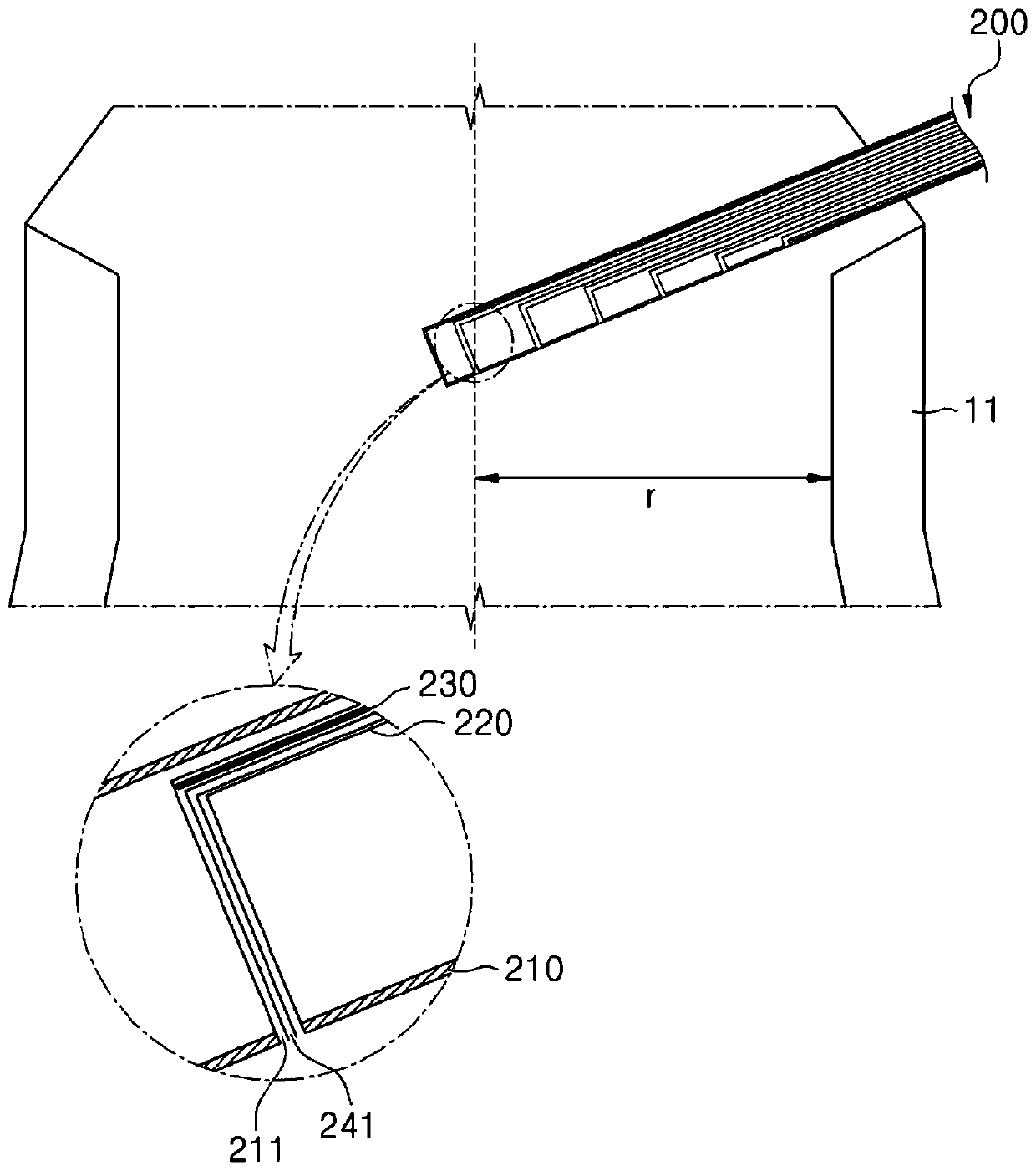
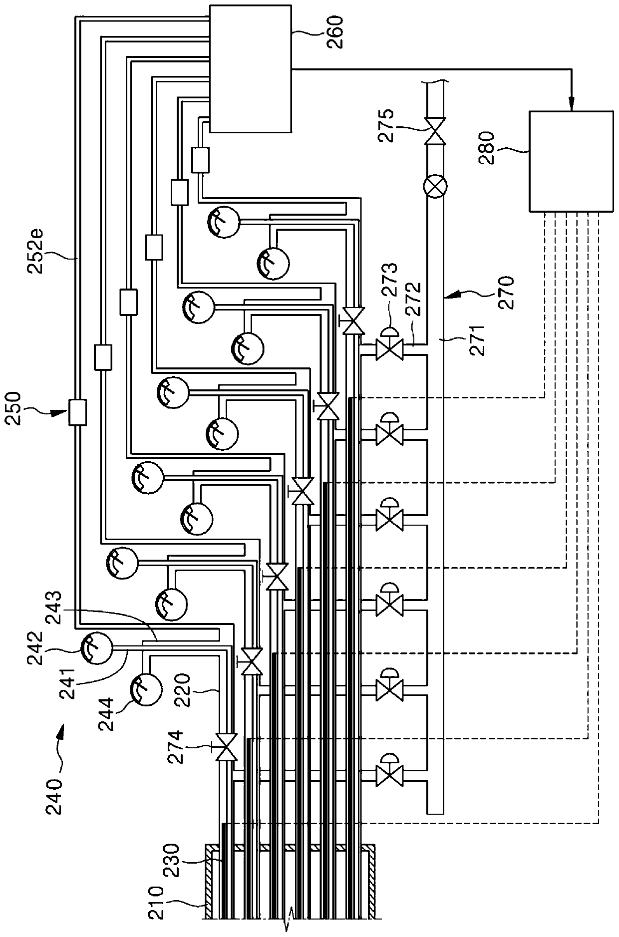
The present invention provides a gas treatment apparatus and an operation method using the same, the gas treatment apparatus comprising: a cylindrical body which can pass through a container for a to-be-treated material and has openings that can be exposed within the container; introduction tubes which are connected to the openings respectively so as to introduce gas from the container; first detectors which are installed in the introduction tubes, respectively; second detectors which are connected to the introduction tubes, respectively; gas purifiers which are connected to the introduction tubes, respectively; a third detector which is connected to the gas purifiers; and a calculation unit which can calculate the heat values of gas according to a plurality of positions by using temperatures and flow rates of the gas, detected by the first detectors and the second detectors, and can calculate utilization rates of the gas according to the plurality of positions by using a component detection result of the gas detected by the third detector, whereby the gas can be introduced from the container for a to-be-treated material and effectively purified, and various states of the gas can be detected.

Description

technical field [0001] The present disclosure relates to a gas processing facility and a method of operating using the same, and more particularly to a gas processing facility and a method of operating using the gas processing facility that can The gas is introduced from the container for the material to be processed and the gas is efficiently purified and various states of the gas can be detected. Background technique [0002] A blast furnace is a high-temperature, high-pressure reactor used to produce molten steel. The series of processes used to produce molten steel in a blast furnace is known as blast furnace treatment or blast furnace process. The process is as follows. Blast furnace charges - eg, iron ore, sinter and coke - are loaded into the blast furnace. Thereafter, hot air and pulverized coal are blown into the lower portion of the blast furnace, and coke and pulverized coal are burned by the hot air to generate reducing gas. Then, reducing gas is passed to th...

Claims


Application Information

Patent Timeline
IPC IPC(8): C21B7/00C21B7/24F27B1/28F27D21/00F27D21/04
CPCC21B7/002C21B7/24C21B13/0073C21B2100/44F27B1/18F27B1/28F27D17/008F27D21/00F27D21/0014F27D21/04Y02P10/134
Inventor 郑镇坰孙炳连金丞甫张贤柱陆相锡金钟贤
Owner POHANG IRON & STEEL CO LTD
Learn More