Supercharge Your Innovation With Domain-Expert AI Agents!

Numerical control device, program conversion device, numerical control method, and program conversion method

A technology of numerical control device and processing program, applied in the direction of electrical program control, automatic control device, feeding device, etc., can solve the problems of lack of processing accuracy and processing quality, and achieve the effect of improving processing accuracy and processing quality

Active Publication Date: 2019-08-06
MITSUBISHI ELECTRIC CORP
View PDF9 Cites 0 Cited by
  • Summary
  • Abstract
  • Description
  • Claims
  • Application Information

AI Technical Summary

Problems solved by technology

There is a problem that the desired machining accuracy and machining quality cannot be obtained if machining is performed on the restored curved path only by estimation from the command point approximated as described above.

Method used


Image

  • Numerical control device, program conversion device, numerical control method, and program conversion method
  • Numerical control device, program conversion device, numerical control method, and program conversion method
  • Numerical control device, program conversion device, numerical control method, and program conversion method

Examples


Embodiment approach 1

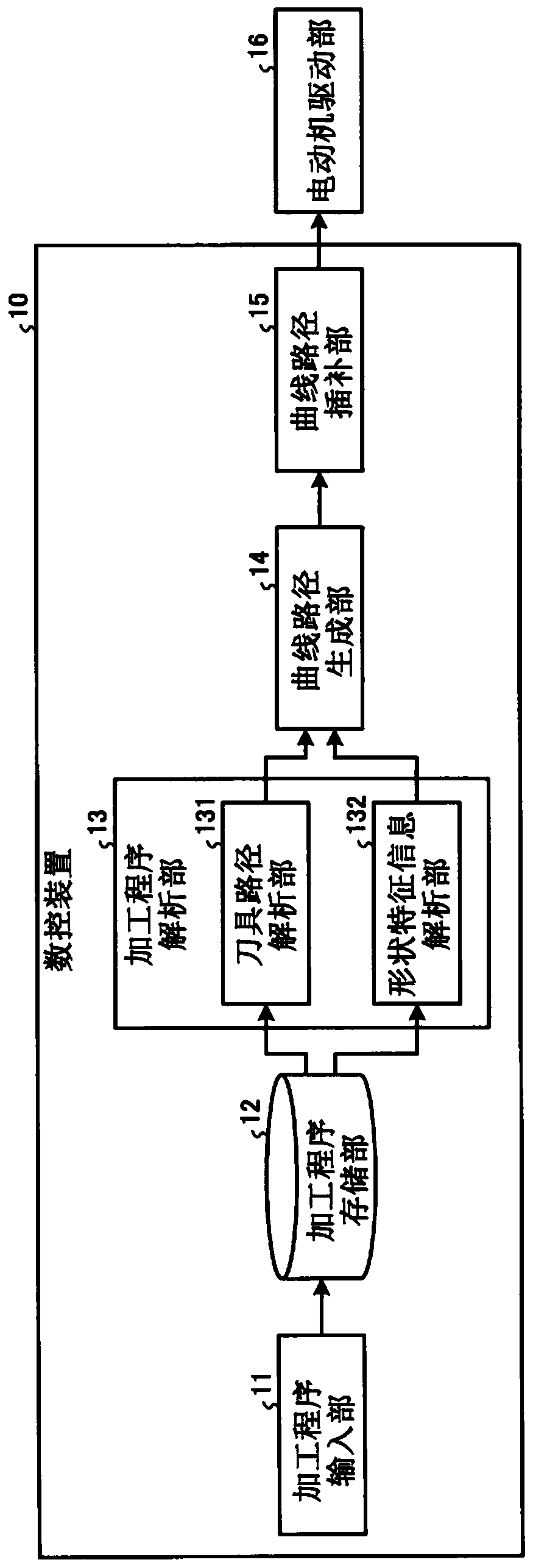
[0049] figure 1 It is a figure which shows the structural example of the numerical control device concerning Embodiment 1 of this invention. The numerical control device 10 is a device for performing numerical control on a machine tool (not shown) via a motor drive unit 16 .

[0050] The numerical control device 10 has: a machining program input unit 11, which receives a machining program input from the outside; a machining program storage unit 12, which stores the machining program; a machining program analysis unit 13, which analyzes the machining program; a curved path generation unit 14, which generates a curved path based on the analysis result of the machining program; and a curved path interpolation unit 15, which performs interpolation processing on the curved path. In addition, the machining program analyzing unit 13 has: a tool path analyzing unit 131 which analyzes the machining program to obtain command positions constituting the tool path; and a shape feature inf...

Embodiment approach 2

[0087] Figure 7 It is a figure which shows the structural example of the numerical control device concerning Embodiment 2. exist Figure 7 In , the same reference numerals are assigned to the same components as those of the numerical control device 10 described in the first embodiment. In the present embodiment, the description of the components common to the numerical control device 10 is omitted.

[0088] The numerical control device 10a according to the second embodiment is configured by replacing the machining program analysis unit 13 and the curved path generation unit 14 of the numerical control device 10 according to the first embodiment with the machining program analysis unit 13a and the curved path generation unit 14a, respectively, and A tool data input unit 21 , a tool data storage unit 22 , a shape data input unit 23 , a shape data storage unit 24 , and a shape characteristic information calculation unit 25 are added. In addition, the shape feature information...

Embodiment approach 3

[0165] In Embodiment 2, the numerical control device calculates shape feature information based on movement commands, tool data, and shape data included in a machining program, and generates a curved path in consideration of the calculated shape feature information. On the other hand, in this embodiment, it will be described that a curved path similar to that in Embodiment 2 can be generated even in a numerical control device that does not have a function of converting a machining program in consideration of shape characteristic information and generating a curved path in consideration of shape characteristic information. A program conversion device for processing programs.

[0166] Figure 28 It is a diagram showing a configuration example of a program conversion device according to Embodiment 3. The program conversion device 30 according to Embodiment 3 includes a machining program input unit 11, a machining program storage unit 12, a machining program analysis unit 13a, a ...


PUM


Abstract

A numerical control device according to the present invention includes: a machining-program input unit (11) that allows input of a machining program dictating movement instructions for a tool or movement instructions for an object to be machined; and a curved-path generating unit (14) that generates a curved path on the basis of the movement instructions and shape feature information representingfeatures of the shape of a tool path passing through instructed positions as instructed according to the movement instructions.

Description

technical field [0001] The invention relates to a numerical control device constituting a numerical control working machine, a program conversion device for converting a numerical control machining program, a numerical control method and a program conversion method. Background technique [0002] In order to process the object to be processed, the NC machine tool uses a NC machining program (hereinafter referred to as the "processing program") that describes the movement command, which is used to make the object to be machined or the tool loaded on the NC machine tool according to the preset move along the defined path. The machining program is created by, for example, a commercially available CAD (Computer-Aided Design) / CAM (Computer Aided Manufacturing) device, and is described in a predetermined format of character strings such as G codes and macro sentences. Here, the G code refers to one of the command codes used in numerical control, and is the command code described i...

Claims


Application Information

Patent Timeline
IPC IPC(8): G05B19/4103B23Q15/00
CPCG05B19/4103
Inventor 金子弘树西胁健二入口健二津田刚志
Owner MITSUBISHI ELECTRIC CORP
Features
  • R&D
  • Intellectual Property
  • Life Sciences
  • Materials
  • Tech Scout
  • Unparalleled Data Quality
  • Higher Quality Content
  • 60% Fewer Hallucinations
Learn More