
A booster for an aircraft

A supercharging device and aircraft technology, which is applied to parts of elastic fluid pumping devices, machines/engines, non-variable pumps, etc., can solve the problem of small axial size, function and structure that cannot meet the requirements of combined wing aircraft Work requirements, high single-stage booster ratio, etc., to achieve the effect of small axial size, compact structure, and small loss along the way

Active Publication Date: 2020-07-03
ANHUI UNIVERSITY OF TECHNOLOGY
View PDF1 Cites 0 Cited by
  • Summary
  • Abstract
  • Description
  • Claims
  • Application Information

AI Technical Summary

Problems solved by technology

Existing centrifugal compressors, such as known centrifugal compressors (CN104343734A), have been obtained on small-sized turbojet engines due to the characteristics of high single-stage boosting ratio, simple structure, small axial dimension, and large stable operating range. Wide range of applications, although its working principle is suitable for the application requirements of combined wing aircraft, however, the function and structure of the base and impeller cannot meet the working requirements of combined wing aircraft

Method used


Image

  • A booster for an aircraft
  • A booster for an aircraft

Examples


Embodiment Construction

[0027] The present invention will be further described below in conjunction with the accompanying drawings and specific embodiments.

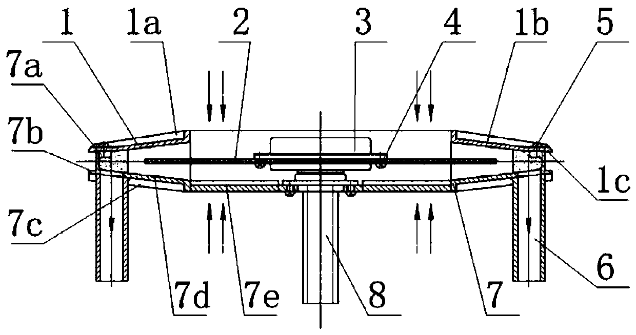
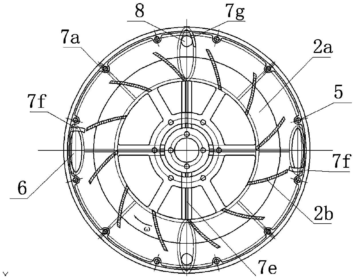
[0028] figure 1 Is the front view of the aircraft pressurization device. The frame of the power distributor 3 is fixedly connected with the flange at the center of the machine base 7 by bolts, the output disk of the power distributor 3 and the inner disk of the spoke disc of the impeller 2 are fixedly connected by the lower screw 4, and the upper cover 1 and the machine base 7 The inner protrusion 7a of the inner body is fixedly connected by the upper screw 5, and after assembly, the main body of the supercharging device in the shape of a flying saucer is formed. The upper rail surface 1c of the upper cover 1 and the lower rail surface 7b of the base 7 form a ring-shaped track, the lower cone surface 1b of the upper cover 1 and the upper cone surface 7d of the base 7 form the working chamber and the air collection chamber of the impeller, the ...


PUM


Abstract

The invention discloses an aircraft supercharging device, and belongs to the technical field of aircrafts. The device comprises an upper cover, an impeller, a machine base and an air storage pipe; theupper cover and the machine base are fixedly connected to form an axisymmetric annular space, the impeller is positioned between the upper cover and the machine base, the blades of the impeller are positioned in the annular space, and the annular space which is larger than the maximum radius of the blades forms an air collecting cavity. Four hollow pipes with oval section are fixedly connected with the machine base and communicate with the air collecting cavity to form the air storage pipe. When the impeller rotates at a high speed, airflow is sucked from the central part of the impeller, andis accelerated by the blades and then enters the air collecting cavity and continues to flow along the circumference, under the action of a side guide plate and a rear guide plate, the air flow enters the air storage pipe to be subjected to speed reduction and supercharging. The supercharging device adopts an impeller with axially symmetric blades, an air flue with gradually reduced cross sectional area and the annular air collecting cavity, and is characterized by low airflow loss, high working efficiency; and the air flow can be automatically distributed according to the working load of theair storage pipe, and the requirement for the attitude control of the combined wing aircraft is met.

Description

Technical field: [0001] The invention belongs to the technical field of combined-wing aircraft, and in particular relates to an aircraft supercharging device. Background technique: [0002] Combined-wing aircraft is a combination of special-type rotor and fixed-wing aircraft. The flight attitude of the aircraft is controlled by the jet aerodynamic force of high-speed airflow. It has the advantages of both rotor and fixed-wing aircraft. Functions such as hovering and flexible steering have broad application prospects in both military and civilian fields. Aircraft supercharging device is a compressor that produces high-speed airflow. The impeller of the compressor and the rotor rotate in reverse at high speed to generate high-speed airflow and flight lift respectively, which can meet the working requirements of the combined-wing aircraft. Existing centrifugal compressors, such as known centrifugal compressors (CN104343734A), have been obtained on small-sized turbojet engines ...

Claims


Application Information

Patent Timeline
Patent Type & Authority Patents(China)
IPC IPC(8): F04D1/00F04D29/42F04D29/44F04D29/28F04D29/00
CPCF04D1/00F04D29/002F04D29/284F04D29/4206F04D29/441
Inventor 张玉华陈华张维王孝义熊亮
Owner ANHUI UNIVERSITY OF TECHNOLOGY
Learn More