Optically Excited Infrared Thermography Defect Detection Method Based on Structured Sparse Decomposition

A technology of infrared thermal imaging and sparse decomposition, which is applied in the field of light-excited infrared thermal imaging defect detection based on structured sparse decomposition, can solve the problems of time-consuming and poor accuracy of variational Bayesian tensor decomposition method, and achieve suppression Effects of noise, detection rate improvement, and contrast enhancement

Active Publication Date: 2021-10-22
四川沐迪圣科技有限公司
View PDF22 Cites 0 Cited by
  • Summary
  • Abstract
  • Description
  • Claims
  • Application Information

AI Technical Summary

Problems solved by technology

But these methods have poor accuracy for detecting defects on complex and irregular surfaces, among them, the variational Bayesian tensor decomposition method is very time-consuming

Method used


Image

  • Optically Excited Infrared Thermography Defect Detection Method Based on Structured Sparse Decomposition
  • Optically Excited Infrared Thermography Defect Detection Method Based on Structured Sparse Decomposition
  • Optically Excited Infrared Thermography Defect Detection Method Based on Structured Sparse Decomposition

Examples


Embodiment

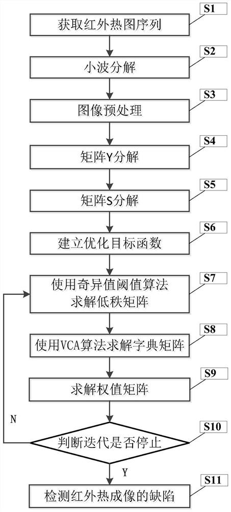
[0037] figure 1 It is a flow chart of the light-stimulated infrared thermal imaging defect detection method based on structured sparse decomposition of the present invention.

[0038] For the heat waves generated under the heating of the light source, when defects of different material properties are encountered inside the test piece, different heat densities will appear. By obtaining the surface temperature signal of the test piece, it will be displayed on the computer as a pseudo-color image. In the reflection mode (the thermal imager and the light source are on the same side), when there is a heat-insulating defect inside the specimen, the defect area will appear as a high-temperature area due to heat accumulation; when there is an endothermic defect inside the specimen, the defect area will appear as a It is a low-temperature area, and the distribution of defects is usually characterized by spatial sparseness. The location and number of defects can be determined by observi...

example

[0090] In order to evaluate the algorithm proposed by the present invention, five defect detection algorithms were selected for comparison, namely principal component analysis (PCA), independent component analysis (ICA), thermal signal reconstruction (TSR), pulse phase method (PPT) and variable Decibel Bayesian Tensor Factorization (EVBTF). In order to evaluate the defect detection effect and efficiency of each algorithm, three evaluation indicators are used, which are F-score, signal-to-noise ratio (SNR) and algorithm running time.

[0091] The definition of F-score is as follows:

[0092]

[0093] Among them, Precision is the precision rate, and Recall is the recall rate, which is defined as follows:

[0094]

[0095] Among them, TP represents the number of defects that are actually detected and detected, FP represents the number of defects that are actually not defective but are detected as defects, FN represents the number of defects that are actually not detected, ...


PUM


Abstract

The invention discloses a light-excited infrared thermal imaging defect detection method based on structured sparse decomposition. By performing wavelet decomposition on each frame image of the heat map sequence, only the low-frequency part is reserved to form a new heat map sequence and arrange them sequentially. Restructured into a new matrix, the new matrix is ​​decomposed into a low-rank matrix, the sum of a sparse matrix and a noise matrix, where the low-rank matrix represents the background of the thermal image, and the sparse matrix represents the defects in the thermal image. The sparse matrix is ​​further decomposed into the product of a dictionary matrix and a weight matrix, where the dictionary matrix is ​​used to characterize the different thermal modes of different defects on the same specimen, and the weight matrix has sparse constraints and non-negative constraints. The low-rank matrix is ​​solved by the singular value threshold decomposition method, the dictionary matrix is ​​solved by the vertex component analysis method, the weight matrix is ​​solved by the multiplier alternating direction method, and finally the sparse matrix is ​​reconstructed into a defect image matrix, so as to realize the defect detection of infrared thermal imaging .

Description

technical field [0001] The invention belongs to the technical field of non-destructive testing, and more specifically relates to a light-stimulated infrared thermal imaging defect detection method based on structured sparse decomposition. Background technique [0002] Non-destructive testing technology is an important means to control product quality and ensure the safe operation of in-service equipment. Infrared thermal imaging detection technology is to measure the temperature through the corresponding relationship between the change process of the radiation energy of the object and the temperature, so as to judge the physical characteristic information of the object. Optically stimulated infrared thermal imaging uses the active heating method of the light source to detect various defects on the surface and inside of the object, which can realize the rapid detection of defects in a wide range of different depths. In recent years, it has been widely used in the field of non...

Claims


Application Information

Patent Timeline
Patent Type & Authority Patents(China)
IPC IPC(8): G01N25/72
CPCG01N25/72
Inventor 高斌刘丽
Owner 四川沐迪圣科技有限公司
Why Eureka
Try Eureka