
A cavity-backed dual-frequency common-aperture antenna based on structure multiplexing

A common-aperture and back-cavity technology is applied to the structural form of radiating elements, antenna arrays and antennas that are powered independently, and can solve the problems of low antenna aperture utilization efficiency and insufficient isolation between antennas, so as to improve aperture utilization efficiency and solve The effect of insufficient channel isolation and improved isolation

Active Publication Date: 2021-02-05
UNIV OF ELECTRONICS SCI & TECH OF CHINA
View PDF8 Cites 0 Cited by
  • Summary
  • Abstract
  • Description
  • Claims
  • Application Information

AI Technical Summary

Problems solved by technology

[0007] The purpose of the present invention is to solve the problems of low antenna aperture utilization efficiency and insufficient isolation between antennas caused by the separation and placement of traditional dual-frequency common-aperture antenna radiation units with a frequency ratio of less than 8, and propose a cavity-backed antenna based on structural multiplexing. Dual-frequency common-aperture antenna; based on the concept of structural multiplexing, the present invention realizes the integration of two frequency band antenna units, and completes the design index requirements of two frequency band antennas

Method used


Image

  • A cavity-backed dual-frequency common-aperture antenna based on structure multiplexing
  • A cavity-backed dual-frequency common-aperture antenna based on structure multiplexing
  • A cavity-backed dual-frequency common-aperture antenna based on structure multiplexing

Examples


Embodiment Construction

[0023] The present invention will be further elaborated below in conjunction with the accompanying drawings and embodiments.

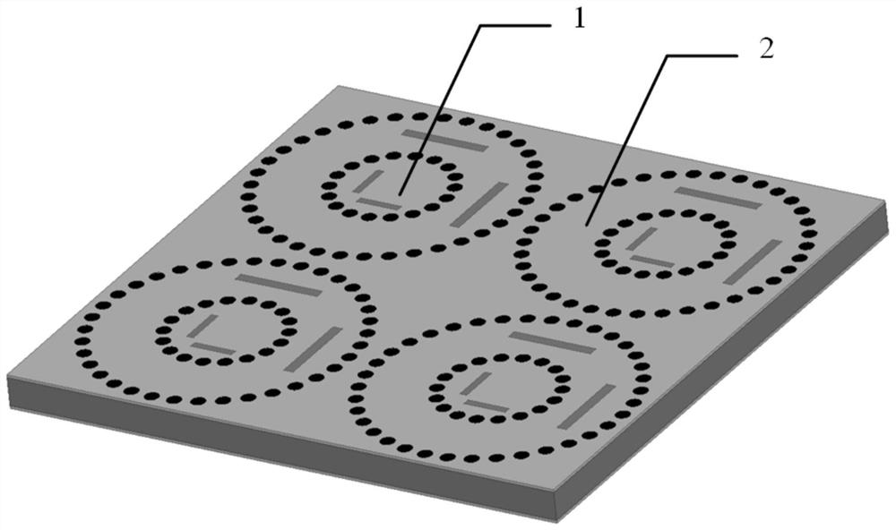
[0024] This embodiment provides a cavity-backed dual-frequency co-aperture array antenna based on structure multiplexing, and its 2×2 radiation structure is as follows figure 1 As shown, wherein, each antenna unit includes: SIW cavity-backed radiation slot antenna 1 and coaxial cavity-backed radiation slot antenna 2; the operating frequency ratio of the antenna in this embodiment is less than 8, and the high and low frequency antennas utilize structural The specificity is integrated without adding additional aperture area, and achieves high isolation under high aperture utilization efficiency.

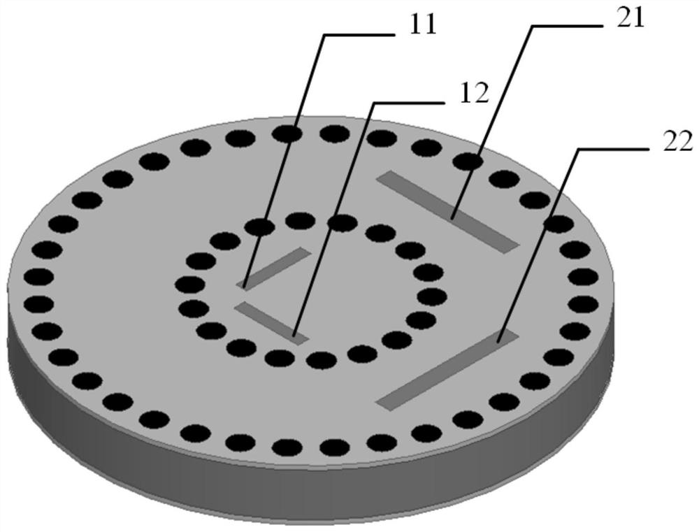
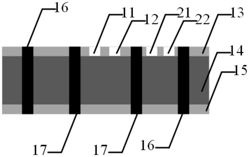
[0025] In this embodiment, the structure of the antenna unit is as follows figure 2 As shown, it includes: the lower metal copper clad layer 15, the dielectric layer 14 and the upper metal copper clad layer 13 stacked in sequence from bottom to top; the upper...


PUM


Abstract

The invention belongs to the technical field of common-aperture antennas, and specifically provides a cavity-backed dual-frequency common-aperture antenna based on structural multiplexing, which is used to overcome the antenna aperture caused by the separate placement of the traditional dual-frequency common-aperture antenna with a frequency ratio of less than 8. There are problems such as low utilization efficiency and insufficient isolation between antennas. The invention utilizes the sealing property of the high-frequency SIW circular cavity-backed radiator itself, so that it constitutes the inner conductor of the low-frequency coaxial cavity-backed radiator, does not occupy the area of ​​the antenna aperture, and realizes a high degree of fusion of the radiation unit structure, which is extremely The aperture utilization efficiency is greatly improved; and, by using the high-pass characteristics of the substrate integrated waveguide, the isolation between high-frequency and low-frequency antennas is greatly improved, and the problem of insufficient channel isolation between antennas in different frequency bands is solved.

Description

technical field [0001] The invention belongs to the technical field of common-aperture antennas, in particular to a cavity-backed dual-frequency common-aperture antenna based on structure multiplexing. Background technique [0002] Antennas working in different frequency bands generally have multiple functional requirements such as different polarizations according to their corresponding application backgrounds. Traditional common-aperture antennas place your antennas in these frequency bands in a common aperture plane to meet different applications. background. Generally speaking, in order to work independently for different functions, multiple antennas of different frequency band antennas are placed separately to avoid mutual interference. So restrained. [0003] Based on the above-mentioned background, traditional common-aperture antennas mostly adopt an interleaving manner for dual-frequency common-aperture separation layout. For example, the literature "Z.Sun, S.S.Zh...

Claims


Application Information

Patent Timeline
Patent Type & Authority Patents(China)
IPC IPC(8): H01Q21/24H01Q21/06H01Q13/18H01Q13/10H01Q1/52H01Q1/50H01Q1/38
CPCH01Q1/38H01Q1/50H01Q1/521H01Q13/106H01Q13/18H01Q21/064H01Q21/24
Inventor 程钰间丁嫣然柏航夏飞扬赵凡刘彦樊勇张波林先其宋开军赵明华
Owner UNIV OF ELECTRONICS SCI & TECH OF CHINA
Learn More