High-voltage STATCOM control platform for switching main and standby dual-control systems
A system switching and control platform technology, applied in flexible AC transmission systems, reactive power adjustment/elimination/compensation, etc., to reduce the difficulty and risk of debugging
- Summary
- Abstract
- Description
- Claims
- Application Information
AI Technical Summary
Problems solved by technology
Method used
Image

Examples
Embodiment 1
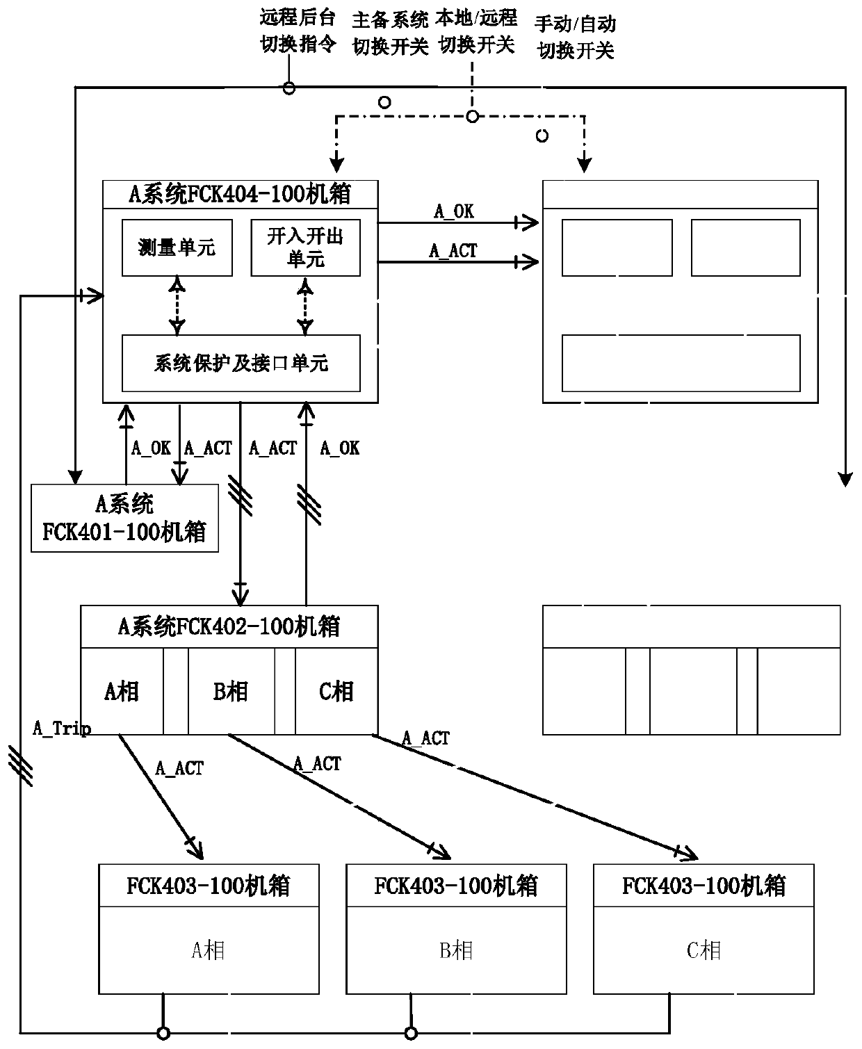
[0019] Example 1: See figure 1 , a high-voltage STATCOM control platform with active and standby dual control systems switching, including A system FCK404-100 chassis, A system FCK401-100 chassis, A system FCK402-100 chassis, B system FCK404-100 chassis, B system FCK401-100 Chassis, FCK402-100 chassis of system B, among them, FCK404-100 chassis of system A and FCK404-100 chassis of system B are active and standby switching chassis, which are mainly responsible for active and Standby switching chassis, A system FCK401-100 chassis and B system FCK401-100 chassis are control and protection chassis, mainly responsible for sampling, input and output, control and protection functions; A and B subsystems each contain a set of control protection Chassis, A system FCK402-100 chassis and B system FCK402-100 chassis are optical fiber transceiver boxes, mainly used for the control of high-voltage STATCOM sub-modules (also called chain links); A and B two sets of subsystems each contain a ...
Embodiment 2
[0049] Embodiment 2. On the basis of Embodiment 1, the A system FCK404-100 chassis of this design is equipped with a measurement unit, a switch input and output unit, a system protection and interface unit, and the system protection and interface unit are respectively connected to the measurement unit and the switch. In and out unit. The structure of the FCK404-100 chassis of system A is the same as that of the FCK404-100 chassis of system B. The FCK404-100 chassis of system A and the FCK404-100 chassis of system B detect the active / passive status of system A / B, and determine their own operating status through the mutual transmission of optical fibers. Each system detects its own status separately to confirm whether A_OK and B_OK are valid. Once A_OK is invalid, it is considered that the self-test is abnormal. At this time, if B_OK is valid, it will switch to the B system. If A_OK and B_OK are invalid at the same time, trip and stop.
PUM
 Abstract
Description
Claims
Application Information
 - Generate Ideas
- Intellectual Property
- Life Sciences
- Materials
- Tech Scout
- Unparalleled Data Quality
- Higher Quality Content
- 60% Fewer Hallucinations
Browse by: Latest US Patents, China's latest patents, Technical Efficacy Thesaurus, Application Domain, Technology Topic, Popular Technical Reports.
© 2025 PatSnap. All rights reserved.Legal|Privacy policy|Modern Slavery Act Transparency Statement|Sitemap|About US| Contact US: help@patsnap.com