Load-bearing gantry crane boom for road and bridge construction

A technology of gantry cranes and single-chip microcomputers, which is applied to cranes, trolley cranes, and traveling mechanisms. It can solve the problems of not being able to meet the needs of use, poor flexibility, and inconvenient adjustment, and achieve the effects of convenient control, increased service life, and convenient adjustment.

Inactive Publication Date: 2019-08-13
徐江穹
View PDF1 Cites 1 Cited by
  • Summary
  • Abstract
  • Description
  • Claims
  • Application Information

AI Technical Summary

Problems solved by technology

[0002] In the prior art: the authorized publication number is that the patent of CN 206798969 U discloses a load-bearing gantry crane hanger for road and bridge construction, including a hanger body and a lifting arm, and the lower end middle part of the lifting arm is fixedly connected to the hanger body. The lower end of the hanger body is symmetrically provided with two support plates on both sides, and the two support plates are provided with a fixing seat on the side close to each other, and a fixing rod is arranged in the fixing seat, and one end of the fixing rod is inserted into the fixing seat The other end of the fixed rod extends to the outside of the fixed seat, and the outer end of the other end of the fixed rod is fixedly connected to one end of the load-bearing arm, and the other end of the load-bearing arm is inserted into the plug on the side wall of the boom. In the groove, there is a guide rod inside the fixed rod, which has poor flexibility, inconvenient adjustment, and cannot meet the needs of use

Method used


Image

  • Load-bearing gantry crane boom for road and bridge construction
  • Load-bearing gantry crane boom for road and bridge construction
  • Load-bearing gantry crane boom for road and bridge construction

Examples


Embodiment Construction

[0055] The technical solutions in the embodiments of the present invention will be clearly and completely described below in conjunction with the accompanying drawings in the embodiments of the present invention. Obviously, the described embodiments are only a part of the embodiments of the present invention, rather than all the embodiments. Based on the embodiments of the present invention, all other embodiments obtained by those of ordinary skill in the art without creative work shall fall within the protection scope of the present invention.

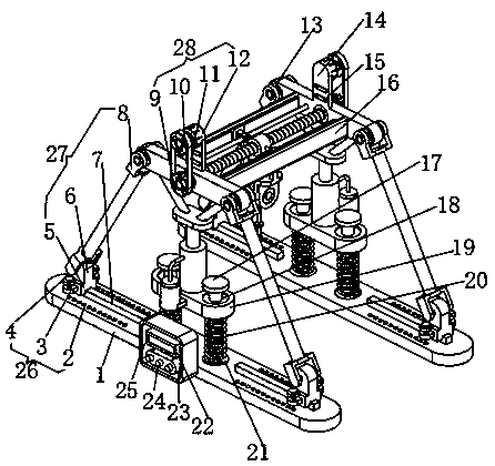
[0056] See Figure 1-3 , The present invention provides a technical solution: a load-bearing gantry crane hanger for road and bridge construction, including a base 1, which has two groups;

[0057] The two sets of bases 1 are arranged symmetrically;

[0058] A control box 25 is fixed on the side of one group of bases 1;

[0059] An open source microcontroller 22 and a wireless transceiver 23 are installed inside the control box 25,

[0060] A...


PUM


Abstract

The invention discloses a load-bearing gantry crane boom for road and bridge construction. The load-bearing gantry crane boom comprises two bases. The two bases are arranged in bilateral symmetry. A control cabinet is fixed to the side face of one base. The control cabinet is internally provided with an open source single-chip microcomputer and a wireless transceiver. A signal amplifier is mountedon the side face of the wireless transceiver. Movable rods are fixed to the tops of the bases. The movable rods are movably connected with mounting seats. The movable rods are sleeved with damping springs. The positions, corresponding to the damping springs, of the bases are provided with countersunk grooves. Information processed through the open source single-chip microcomputer is amplified through the signal amplifier. Amplified signals are transmitted to a remote control terminal through the wireless transceiver. The remote control terminal conducts analysis and processing on the information and conducts remote control on the crane boom. The load-bearing gantry crane boom for road and bridge construction is high in intelligence level, convenient to control and good in safety, and therisk of field operation is avoided.

Description

Technical field [0001] The invention relates to the technical field of road and bridge construction equipment, in particular to a load-bearing gantry crane hanger for road and bridge construction. Background technique [0002] In the prior art: The patent with authorized publication number CN 206798969 U discloses a load-bearing gantry crane hanger for road and bridge construction, which includes a hanger body and a hoisting arm, and the hoisting arm is fixedly connected to the middle of the lower end of the hanger body. Two support plates are symmetrically provided on both sides of the lower end of the hanger body, and the two support plates are provided with fixing seats on the sides close to each other, and a fixing rod is arranged in the fixing seat, and one end of the fixing rod is inserted into the fixing seat The other end of the fixing rod extends to the outside of the fixing seat, and the other end of the fixing rod is fixedly connected to one end of the load-bearing arm...

Claims


Application Information

Patent Timeline
Patent Type & Authority Applications(China)
IPC IPC(8): B66C19/00B66C13/44B66C15/06B66C5/04B66C7/00B66C9/14B66C13/20F16F15/04
CPCB66C5/04B66C7/00B66C9/14B66C13/20B66C13/44B66C15/065B66C19/00F16F15/04
Inventor 徐江穹
Owner 徐江穹
Why Eureka
Try Eureka