Molten salt storage tank heat exchange system

A heat exchange system and storage tank technology, applied in the direction of heat exchanger types, indirect heat exchangers, heat storage equipment, etc., can solve the problems of short life of heating devices, large impact on storage tank design, complex layout structure, etc., and achieve installation Low manufacturing cost, controllable cooling process, safe and reliable operation

Active Publication Date: 2019-08-13
BLUESTAR BEIJING CHEM MACHINERY
View PDF7 Cites 1 Cited by
  • Summary
  • Abstract
  • Description
  • Claims
  • Application Information

AI Technical Summary

Problems solved by technology

[0004] In addition, the molten salt heat storage system has been out of service for a long time, and when it is put into operation again, it is necessary to supply heat to the solidified or viscous molten salt medium in the tank to liquefy it. The traditional solution uses electric heating rods to heat the molten salt in the storage tank. Salt medium heating, this method needs to arrange a large number of heating rods and cables; and

Method used


Image

  • Molten salt storage tank heat exchange system
  • Molten salt storage tank heat exchange system
  • Molten salt storage tank heat exchange system

Examples


Embodiment Construction

[0036] In order to make the technical means, creative features, goals and effects of the present invention easy to understand, the molten salt storage tank heat exchange system of the present invention will be described below through specific embodiments. Unless otherwise specified, the technical means used in the present invention are methods known to those skilled in the art. In addition, the embodiments should be considered as illustrative rather than limiting the scope of the invention, the spirit and scope of which is defined only by the claims. For those skilled in the art, without departing from the essence and scope of the present invention, various modifications and improvements made to the technical solution of the present invention also belong to the protection scope of the present invention.

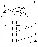
[0037] Such as figure 1 As shown, the molten salt storage tank heat exchange system of the present invention includes a molten salt storage tank 5, and also includes a heate...


PUM


Abstract

The invention discloses a molten salt storage tank heat exchange system. The system includes a molten salt storage tank, a heater, a circulating fan, an airway, an air outlet pipe, air holes and self-opening-closing devices; the circulating fan is arranged outside the storage tank; the inlet of the circulating fan communicates with the internal of the storage tank; the outlet of the circulating fan is connected to the heater; one end of the heater is connected to the circulating fan, and the other end of the heater is connected to the airway; the airway is connected to the air outlet pipe; theair holes are arranged in the air outlet pipe; and the self-opening-closing devices are arranged outside the air outlet pipe and can automatically make the air holes to open or close. Through the system, the self-opening-closing devices can effectively solve the problems of energy loss caused by short circuit phenomenon that, when partial air holes are immersed by molten salt in the storage tank,large amount of hot air used for cyclic heating directly returns to the circulating fan for the next cycle after overflowing through the air holes that are not immersed and does not take part in theheating on the molten salt in the storage tank.

Description

technical field [0001] The invention belongs to the field of molten salt heat storage, and in particular relates to a molten salt storage tank heat exchange system. Background technique [0002] As a clean energy storage medium, molten salt is being more and more widely used in solar thermal power generation, clean heating and other fields. The molten salt storage tank is the core device of the molten salt energy storage system. When the molten salt energy storage system is put into operation for the first time, before the molten salt is introduced into the storage tank, the air in the tank and the tank body need to be preheated to reduce thermal fusion. The temperature difference of the salt entering the storage tank avoids unfavorable phenomena such as deformation of the tank due to uneven stress of the tank caused by hot molten salt entering the tank, and ensures the smooth progress of the salt feeding process. [0003] In addition, the molten salt needs to maintain a ce...

Claims


Application Information

Patent Timeline
IPC IPC(8): F28D20/00
CPCF28D20/0034F28D2020/0047F28D2020/0078Y02E60/14
Inventor 王林司继松林子佳代春雷赵国峰杨海占张学博
Owner BLUESTAR BEIJING CHEM MACHINERY
Why Eureka
Try Eureka