
Microseismic damage reconstruction-based mining-induced stress evaluation method

A technology of dynamic stress and microseismic, applied in seismology, force measurement, seismic signal processing, etc., can solve the problems of lack of physical and mechanical correlation, calculation result error, and difficulty in real-time inversion, etc., and achieve obvious physical and mechanical significance and time-effectiveness High performance, suitable for programming effect

Active Publication Date: 2019-08-13
CHINA UNIV OF MINING & TECH
View PDF13 Cites 4 Cited by
  • Summary
  • Abstract
  • Description
  • Claims
  • Application Information

AI Technical Summary

Problems solved by technology

However, the seismic wave velocity tomography technology indirectly calculates the mining stress distribution based on the P-wave velocity distribution, and in the calculation process, a certain number of microseismic events are required as the original data for the inversion, which will inevitably cause problems during the inversion period. The unreasonable assumption that the P-wave velocity must be set as a constant leads to certain errors in calculation results. At the same time, the calculation amount of this technology is generally relatively large, and it is difficult to achieve real-time inversion; based on the evaluation of the spatial distribution of microseismic events, microseismic frequency density distribution and energy density distribution Although it can infer the distribution of mining stress by reflecting the distribution of mining fractures to a certain extent, it lacks obvious physical and mechanical correlation

Method used

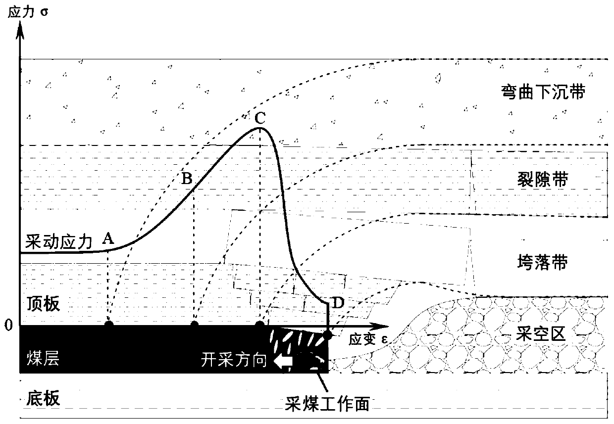

Image

  • Microseismic damage reconstruction-based mining-induced stress evaluation method
  • Microseismic damage reconstruction-based mining-induced stress evaluation method
  • Microseismic damage reconstruction-based mining-induced stress evaluation method

Examples


Embodiment 1

[0048] Example Analysis Select the microseismic monitoring data of a coal mine working face during the mining stage for analysis. Since the mining speed of this working face is approximately uniform and stable, and the average daily footage is 1.2m, the calculation of the present invention is finally explained using the strain-time model as an example. Implement the present invention according to the idea of ​​the present invention:

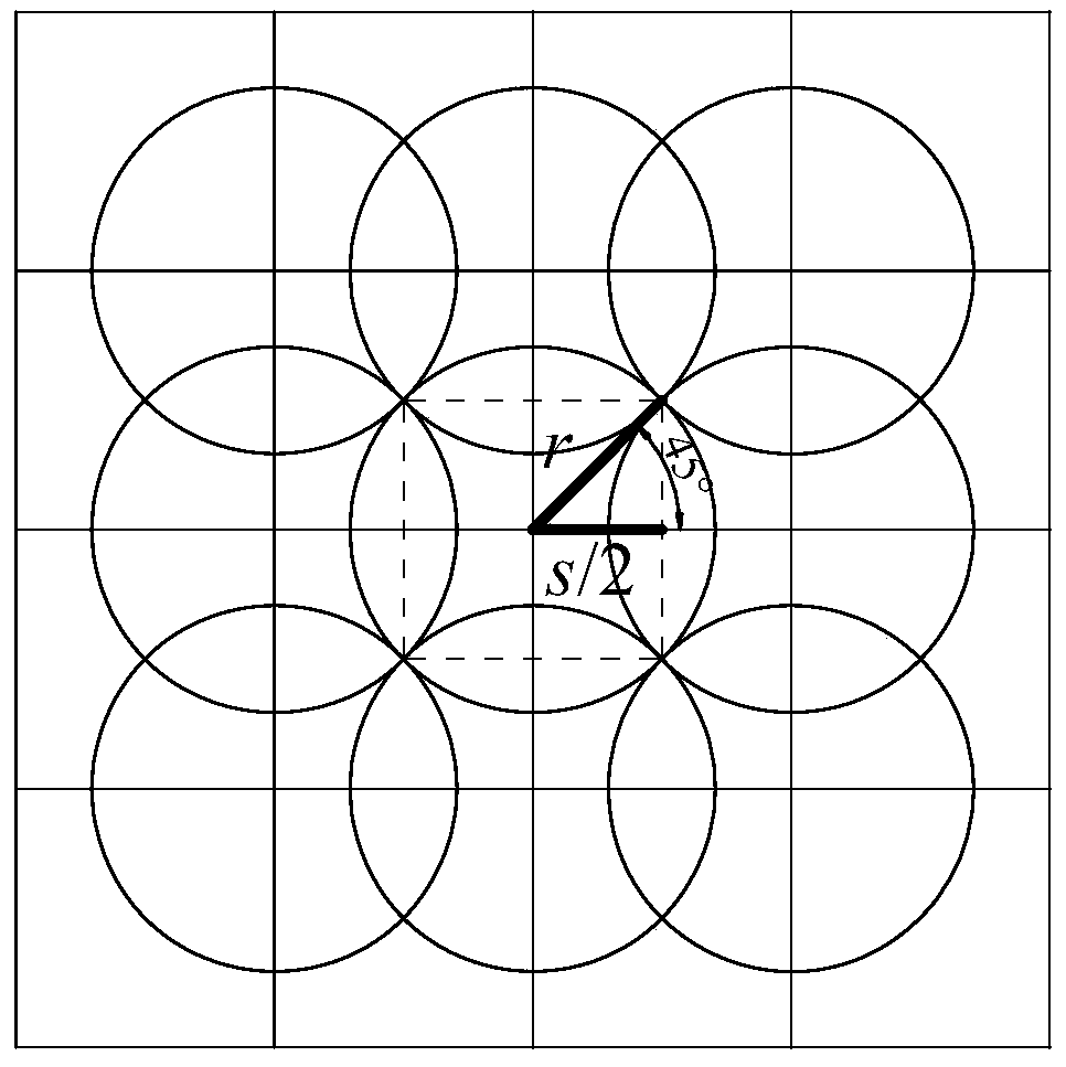
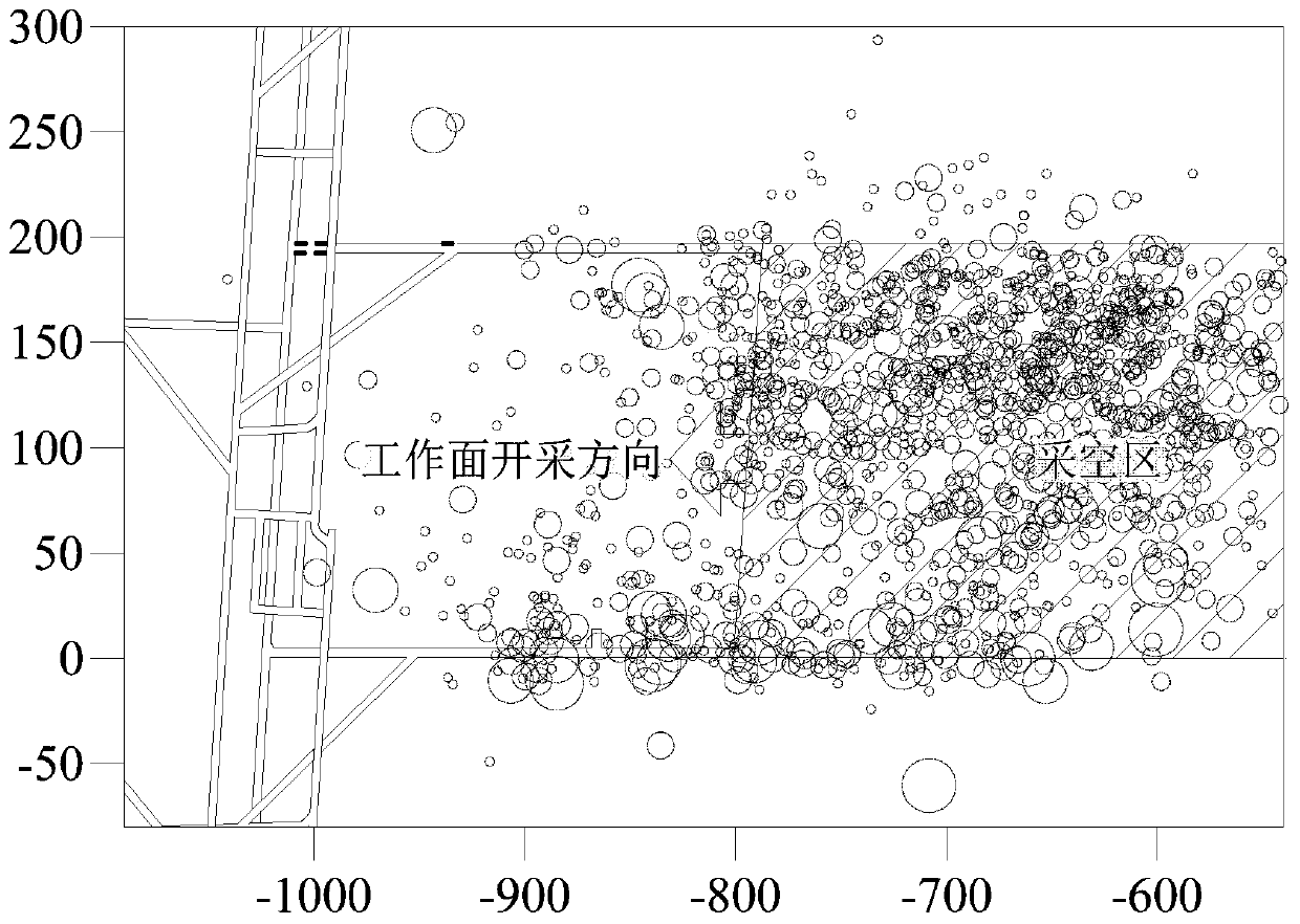
[0049] (1) According to the spatial distribution of microseismic events such as image 3 As shown; the evaluation area is divided into three-dimensional grids, the grid spacing s is 10m, the statistical slip radius r is 30m, and the cumulative deformation energy ε at each grid node is calculated by the cumulative method Ei and coal-rock loading elapsed time Δt i , and then using the interpolation calculation method, it can be obtained as follows Figure 4 The spatial distribution of cumulative deformation energy and Figure 5 The spatial distr...


PUM


Abstract

The invention relates to a microseismic damage reconstruction based mining-induced stress evaluation method, and is suitable for use in the field of microseismic monitoring in the field of mine safety. The method specifically comprises the steps of carrying out grid partition on an evaluation area; calculating cumulative deformation energy Epsilon Ei and a microseismic event number or a coal rockloading time Delta ti of each grid node by adoption of an accumulation method; finding out a maximum cumulative deformation energy value max {Epsilon Ei} of the evaluation area and calculating averagecumulative deformation energy Epsilon F; and obtaining mining-induced stress distribution on the basis of calculating damage parameter D distribution. The method has obvious physical and mechanical significance, has involved parameters which are clear and strong in universality and operability, is suitable for programming, has good application feasibility, and can realize approximate real-time inversion of mining-induced stress in coal seam mining processes.

Description

technical field [0001] The invention relates to a mine mining stress assessment method, in particular to a mining stress assessment method based on microseismic damage reconstruction suitable for the field of mine safety microseismic monitoring. Background technique [0002] Mining stress is a secondary stress after the original stress in the surrounding rock body of the underground mining space is redistributed by the mining disturbance. Knowing the distribution characteristics of this stress is one of the indispensable important basis and work in the mining production process such as working face design, stop production line design, coal pillar design, safety protection design, support design and so on. [0003] Since the disturbance of coal seam mining is a dynamic process, the mining stress also changes dynamically all the time, which ultimately makes it difficult to directly observe and quantitatively describe this "black box" process in a large scale. At present, the ...

Claims


Application Information

Patent Timeline
IPC IPC(8): G01V1/28G01V1/30G01L1/25
CPCG01V1/30G01V1/288G01L1/255G01V2210/616
Inventor 蔡武窦林名曹安业巩思园袁莎莎
Owner CHINA UNIV OF MINING & TECH
Learn More