Subway car end underframe structure

A technology for subway cars and underframes, which is applied to railway car body parts, underframes, and wheel guards/buffers for railway vehicles, etc. Avoid excessive local force, improve space utilization, and improve the effect of force conduction paths

Pending Publication Date: 2019-08-16
CRRC CHANGCHUN RAILWAY VEHICLES CO LTD
View PDF0 Cites 6 Cited by
  • Summary
  • Abstract
  • Description
  • Claims
  • Application Information

AI Technical Summary

Problems solved by technology

[0003] At present, in the rail transit industry, there are many forms of end underframes. According to the different connection forms with the coupler, they are roughly divided into two types. One is bolt connection. Refer to figure 1 , that is, the coupler mounting surface is perpendicular to the longitudinal direction of the underframe, and the underframe needs to be connected to the coupler through the traction beam to transmit traction and braking forces. Due to the need to consider various working conditions, the overall size of the coupler seat is very large, resulting in the traction force connected to it. The beam coupler seat also needs enough space to connect with it, which will take up a lot of space under the chassis, which will affect the equipment layout and wiring requirements of other systems
Due to the influence of the fixed distance of the vehicle, the distance between the bolsters is too long, and the bolsters are only connected by two buffer beams, and the force is directly transmitted to the bolster beams through the buffer beams without spreading the force. The section of the buffer beams changes rapidly, which is extremely It is easy to cause stress concentration, so a large number of thick plate welding is used for this type of end chassis, which makes it difficult to control the weight of the vehicle
[0004] The other is a pin connection, see figure 2 , that is, the coupler installation surface is inserted into a specific position of the underframe, and is connected with the underframe through a pin shaft. Since this connection is an embedded connection, in order to avoid the installation space and the coupler body space, the end underframe needs to have a structure in front of the installation. The variable cross-section treatment is adopted on the surface, and due to the small space at the joint and the high strength requirement, it is necessary to use a large number of thick plates for welding, and the deformation after welding is large, resulting in poor manufacturability and post-maintenance

Method used


Image

  • Subway car end underframe structure
  • Subway car end underframe structure
  • Subway car end underframe structure

Examples


Embodiment Construction

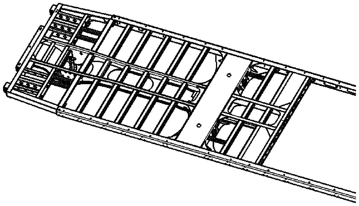
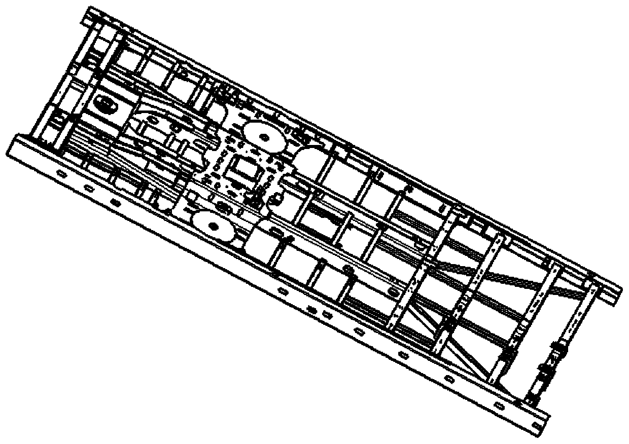
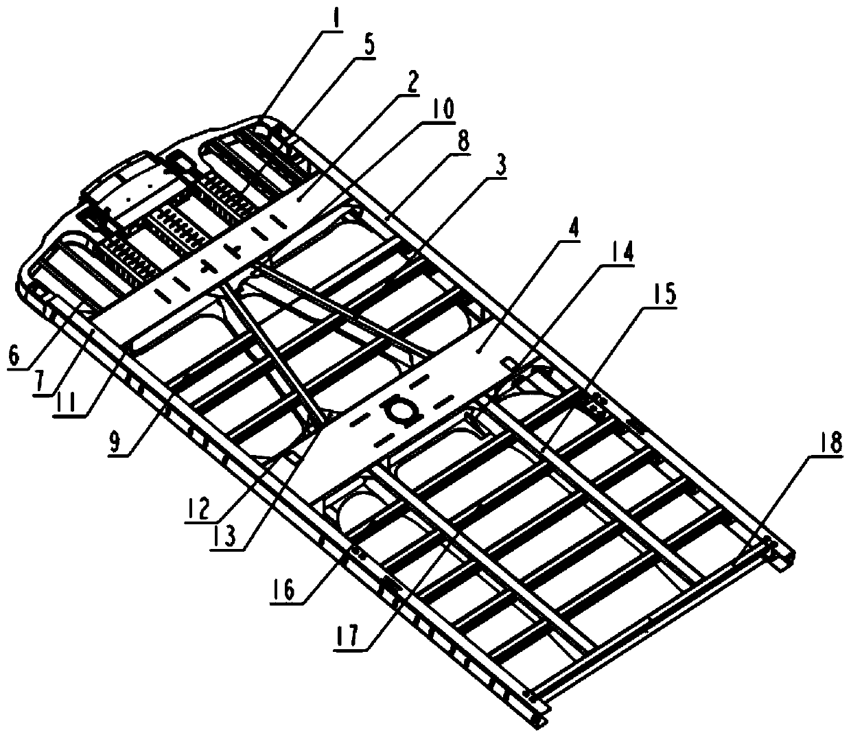
[0023] refer to image 3 , the composition of the end underframe in the present invention includes: front anti-climbing device composition 1, coupler seat composition 2, buffer beam composition 3, corbel composition 4, crush box composition 5, connecting beam 6, left carbon steel side beam Composition 7, right carbon steel side beam composition 8, inclined floor beam 9, special-shaped patch 10, patch 11, vertical panel 12, isosceles patch 13, stiffener plate 14, longitudinal beam composition 15, floor beam 16, long Floor beam 17, main beam 18. The front anti-climbing device consists of 1 to prevent the car body from climbing up during the vehicle collision process, and the two ends are welded to the left carbon steel side beam composition 7 and the right carbon steel side beam composition 8; the crush box composition 5 is welded to the front end anti-climbing device. Between the crawler component 1 and the coupler seat component 2, when the vehicle collides, deformation occur...


PUM


Abstract

The invention relates to a subway car end underframe structure. The subway car end underframe structure comprises a front-end anti-creeper assembly, a crushing box assembly, a coupler seat assembly and a sleeper beam assembly. The subway car end underframe structure is characterized in that the crushing box assembly is welded between the front-end anti-creeper assembly and the coupler seat assembly; connecting beams are arranged on the two side parts between the front-end anti-creeper assembly and the coupler seat assembly; a buffer beam assembly is connected between the coupler seat assemblyand the sleeper beam assembly; the tail end of the end part of the underframe is a main cross beam; and a longitudinal beam assembly is connected between the sleeper beam assembly and the main cross beam; and the front-end anti-creeper assembly, the crushing box assembly, the coupler seat assembly, the buffer beam assembly, the sleeper beam assembly, the longitudinal beam assembly and the main cross beam are sequentially connected into a whole, and the two sides of the whole structure and carbon steel side beam assemblies are welded into a closed structure. The subway car end underframe structure is exquisite and concise, the arrangement of the cross beam and the longitudinal beams is reasonable, and on the premise of ensuring the continuity of force transmission, the installation space and maintainability of other systems are met as far as possible; through the reasonable arrangement of reinforcing parts, the continuity of force transmission is realized through various connectors, andstress concentration and excessive local stress are avoided; light weight requirements are met; and the operability of replacement is ensured, and the maintainability is good.

Description

technical field [0001] The invention belongs to the technical field of rail vehicle bodies, and in particular relates to an underframe structure at the end of a subway car body. Background technique [0002] The underframe supports the car body and is the foundation of the car body. The underframe bears most of the weight of the upper car body and the load, and is connected with the lower bogie (running part) through the corbel. When the train is running, the underframe bears the traction force and various impact forces and other external forces caused by the train running, so the underframe is one of the most important components of the car body, and the end underframe is the main bearing part of the underframe. When the force is applied, the end chassis bears the brunt and bears the most severe, complex, and varied load impacts. It must have sufficient strength and rigidity, so it is particularly important to design an end chassis that meets various requirements. [0003...

Claims


Application Information

Patent Timeline
Patent Type & Authority Applications(China)
IPC IPC(8): B61F1/10B61F1/14B61F19/04
CPCB61F1/10B61F1/14B61F19/04
Inventor 李永涛刘晓芳刘杰李克铭段鹏飞
Owner CRRC CHANGCHUN RAILWAY VEHICLES CO LTD
Why Eureka
Try Eureka