an inflator

A technology of an inflator and an inflatable tube, which is used in containers to prevent mechanical damage, thin material handling, packaging, etc. Inflation efficiency, incision leveling, and the effect of improving incision quality

Active Publication Date: 2020-10-30
XIAMEN AMESON NEW MATERIAL INC
View PDF12 Cites 0 Cited by
  • Summary
  • Abstract
  • Description
  • Claims
  • Application Information

AI Technical Summary

Problems solved by technology

[0003] (1) At present, the existing inflator is used to inflate the closed roll film. The inflation tube with the same aperture is used to inflate the roll film only once. The inflation tube is short and the pores are few, so the inflation stroke is short. And because the roll film is thick, the air valve of the roll film is not easy to open, and sometimes it will not be fully filled.
[0004] (2) The inflated roll film needs to pass through the film cutting device to separate the inflation channel of the roll film before it can be separated from the inflation tube. Since the roll film is soft, wrinkles will occur, and the blade is relatively rigid. When cutting the film, the blade will cut the upper outer film of the roll film and also cut the lower outer film, so that filaments will be produced at the position of the heat sealing line, bringing debris, and the incision will be uneven and jagged, sometimes It will also cut the position of the air valve, causing air leakage
If the roll film is not cut smoothly at the blade position, the roll film will accumulate at the blade opening, and eventually the roll film will be stuck
In addition, when replacing the blade, because the space where the blade is located is narrow and the line of sight is obstructed, if the blade is removed directly at the installation place of the blade, the hand will inevitably come into contact with the edge of the blade, and there is a risk of scratching the hand by the blade
[0005] (3) At present, most of the inflator equipment puts the roll film on the roll film placement rod. The roll film placement rod of many equipment is cylindrical and has a smooth surface. The roll film is directly placed on the smooth cylinder. , this will cause the roll film core to jump when it rotates at high speed, the tension force of the roll film in the film winding rod is insufficient, and the roll film core will continue to rotate due to inertia when the machine stops, and the roll film will wrinkle and will The backlog of the roll film on the film winding rod affects the second start
However, the actual use effect is not ideal, and the tension of the roll film inflatable channel will be insufficient, and there is still a risk that the inflatable tube will pass through the roll film inflatable channel when running at high speed
[0007] (4) The power system of the existing inflator basically adopts gear transmission, including the upper and lower gears that are intermeshed with the roller assembly that drives the roll film forward. The roller assembly generally has two groups, three groups or multiple groups, generally Three groups, the gear assembly of the corresponding driving roller assembly generally also has multiple sets of meshing upper and lower gear sets, the upper and lower gear sets are arranged along the same straight line at a certain distance, and the power gear one meshing with the first gear set is in the two The meshing between the gear sets connects the power gear two of the two gear sets. The power gear one is connected to a motor, and the power gear two is connected to another motor. The two motors drive the power gear to drive the entire transmission system. Currently, large Most of the two motors used are small in power, and the power of the drive system is small. The drive system is completely driven by a gear set. The transmission speed is limited and cannot be effectively improved, so the speed of the roll film inflation transmission cannot be effectively improved.

Method used


Image

  • an inflator
  • an inflator
  • an inflator

Examples


Embodiment Construction

[0040] The present invention will be further described in conjunction with the accompanying drawings and specific embodiments.

[0041] In describing the present invention, it should be understood that the terms "center", "length", "width", "thickness", "upper", "lower", "front", "rear", "left", " The orientation or positional relationship indicated by "right", "vertical", "horizontal", "inner", "outer", "clockwise", "counterclockwise", etc. is based on the orientation or positional relationship shown in the drawings, and is only In order to facilitate the description of the present invention and simplify the description, it does not indicate or imply that the device or element referred to must have a specific orientation, be constructed and operated in a specific orientation, and thus should not be construed as limiting the present invention.

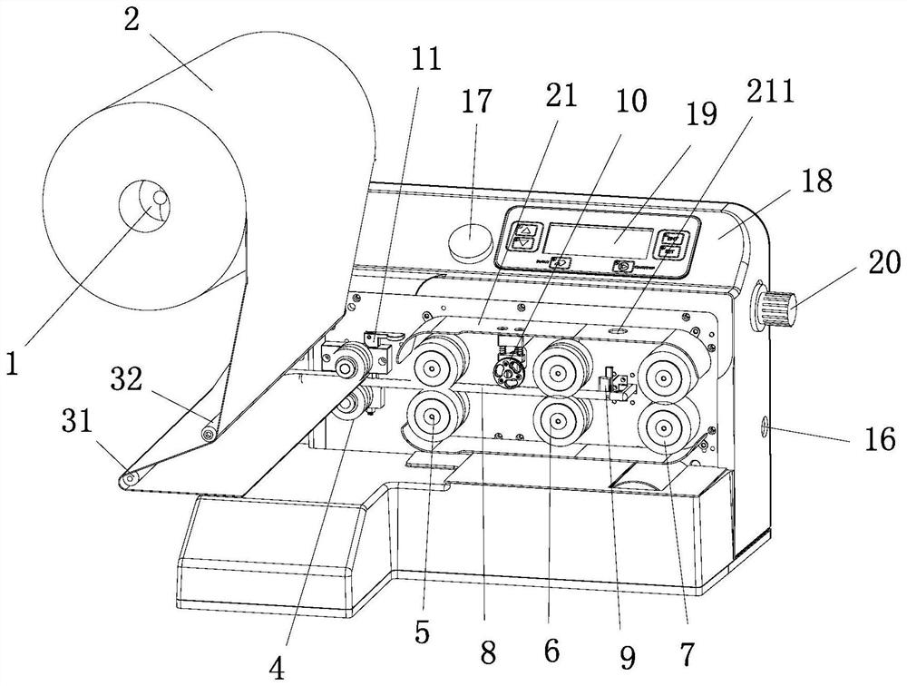
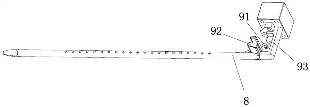
[0042] An inflator, comprising an inflation tube 8 and a pressure wheel assembly 4, a first roller assembly 5 and a second roller ass...


PUM


Abstract

The invention discloses an inflator, and relates to the field of packaging equipment. The inflator comprises an inflating pipe and a pressing wheel assembly, a first roller assembly and a second rolling wheel assembly which are arranged in sequence along the axial direction of the inflating pipe; the surface of the part, between the pressing wheel assembly and the second rolling wheel assembly, ofthe inflating pipe is provided with rows of inflating holes in the axial direction, the inflating pipe is divided into a first inflating section and a second inflating section, and the aperture of the inflating holes of the first inflating section is smaller than the aperture of the inflating holes of the second inflating section; and an inflating channel of a rolling film penetrates through theinflating pipe, the pressing wheel assembly, the first rolling wheel assembly and the second rolling wheel assembly are used for pressing and closing the inflating channel of the rolling film, the first inflating section is used for pre-inflating the rolling film, and the second inflating section is used for inflating the pre-inflated rolling film to be full. The first inflating section opens a valve of a film rolling air column, the second inflating section provides air flow with smaller pressure to fill the air column, the inflating mode of the two sections of inflating holes is adopted, sothat inflating of the rolling film is more full and cannot be exploded, in this way, the inflating efficiency is improved.

Description

technical field [0001] The invention relates to the field of packaging equipment, in particular to an inflator. Background technique [0002] Air column film is widely used in product packaging, and the inflators currently used to inflate air column film still have some shortcomings: [0003] (1) At present, the existing inflator is used to inflate the closed roll film. The inflation tube with the same aperture is used to inflate the roll film only once. The inflation tube is short and the pores are few, so the inflation stroke is short. And because the roll film is thick, the air valve of the roll film is not easy to open, and sometimes it will not be fully filled. [0004] (2) The inflated roll film needs to pass through the film cutting device to separate the inflation channel of the roll film before it can be separated from the inflation tube. Since the roll film is soft, wrinkles will occur, and the blade is relatively rigid. When cutting the film, the blade will cut ...

Claims


Application Information

Patent Timeline
Patent Type & Authority Patents(China)
IPC IPC(8): B65H23/06B65H35/10B31D5/00B65D81/05
CPCB31D5/0073B65D81/052B65H23/06B65H35/10
Inventor 涂宗铃谢继福叶岳团
Owner XIAMEN AMESON NEW MATERIAL INC
Why Eureka
Try Eureka