
Cleaning refrigerating system and method

A refrigeration system, clean technology, applied in refrigerators, refrigeration components, refrigeration and liquefaction, etc., can solve problems such as easy accumulation of lubricating oil, increase in condensation temperature, increase in pressure ratio of refrigeration compressors, etc., to improve operating performance, Guarantee the effect of heat transfer and cleanliness

Inactive Publication Date: 2019-08-16
ANHUI JINMEI ZHONGNENG CHEM IND
View PDF5 Cites 0 Cited by
  • Summary
  • Abstract
  • Description
  • Claims
  • Application Information

AI Technical Summary

Problems solved by technology

[0005] Aiming at the deficiencies of the prior art, the present invention provides a cleaning refrigeration system and method, which solves the problem that the heat exchange surface of the heat exchanger of the refrigeration system is easy to accumulate lubricating oil and generate dirt, which seriously affects the heat transfer effect of the heat exchanger. Increase the heat transfer temperature difference, increase the condensation temperature, and decrease the evaporation temperature, resulting in an increase in the pressure ratio of the refrigeration compressor, an increase in power consumption, and a decrease in the operating performance of the refrigeration system

Method used


Image

  • Cleaning refrigerating system and method

Examples


Embodiment Construction

[0035] The following will clearly and completely describe the technical solutions in the embodiments of the present invention with reference to the accompanying drawings in the embodiments of the present invention. Obviously, the described embodiments are only some, not all, embodiments of the present invention. Based on the embodiments of the present invention, all other embodiments obtained by persons of ordinary skill in the art without making creative efforts belong to the protection scope of the present invention.

[0036] In describing the present invention, it should be understood that the terms "center", "longitudinal", "transverse", "length", "width", "thickness", "upper", "lower", "front", " Back", "Left", "Right", "Vertical", "Horizontal", "Top", "Bottom", "Inner", "Outer", "Clockwise", "Counterclockwise", "Axial", The orientation or positional relationship indicated by "radial", "circumferential", etc. is based on the orientation or positional relationship shown in...


PUM


Abstract

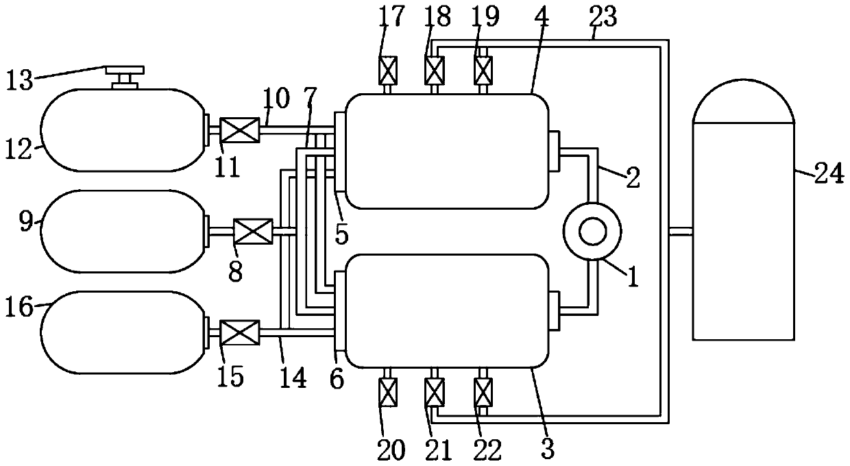
The invention discloses a cleaning refrigerating system, and relates to the related technical field of refrigerating systems. A solution heat exchanger is included. The outer side of the solution heatexchanger is fixedly connected with a refrigeration pipeline. One end of the refrigeration pipeline is fixedly connected with one end of a condenser, and the other end of the refrigeration pipeline is fixedly connected with one end of an evaporator. The other end of the condenser is fixedly connected with one side of a first seal piece, and the other end of the evaporator is fixedly connected with one side of a second seal piece. The invention further discloses a method of the cleaning refrigerating system. The method comprises the steps that A, the refrigeration system is stopped; B, a dry ice machine is started, and a corresponding valve is opened; C, a high-pressure water tank and a corresponding valve are opened; and D, a cleaning water tank and a corresponding valve are opened. The dry ice machine can be used for manufacturing dry ice, after dry ice particles make contact with lubricating oil films and dirt in heat exchange pipes and between various shell pipes, the phenomenon ofembrittlement explosion can happen, accordingly, the lubricating oil films and the dirt can contract and loosen, and then instant gasification and swelling of dry ice particles happen.

Description

technical field [0001] The invention relates to the technical field related to refrigeration systems, in particular to a clean refrigeration system and method. Background technique [0002] The refrigeration principle of a general refrigerator The function of the compressor is to compress the steam with a lower pressure into a steam with a higher pressure, so that the volume of the steam is reduced and the pressure is increased. The compressor sucks the lower-pressure working medium vapor from the evaporator, raises its pressure, and then sends it to the condenser, where it is condensed into a higher-pressure liquid, which becomes a higher-pressure liquid after being throttled by the throttle valve. After the low-pressure liquid is sent to the evaporator, it absorbs heat and evaporates in the evaporator to become a steam with a lower pressure, and then sends it to the inlet of the compressor to complete the refrigeration cycle. A system that uses external energy to transfer...

Claims


Application Information

Patent Timeline
Patent Type & Authority Applications(China)
IPC IPC(8): F25D3/12F25B39/02F25B39/04F28G9/00
CPCF25B39/02F25B39/04F25D3/12F28G9/00
Inventor 张林峰刘建吴亚东李飞张志宏宋雨海王云飞
Owner ANHUI JINMEI ZHONGNENG CHEM IND
Learn More