
A kind of visible light three-layer wave-lined colorful optical fiber and its manufacturing method

A technology of visible light and optical fiber, applied in cladding optical fiber, optical waveguide light guide, multi-layer core/clad optical fiber, etc., can solve the problems of colored light irradiation, quietness, and the existing technology of colorful lighting without ordinary mixed light sources, etc. problem, to achieve the effect of light dispersion and clarity

Active Publication Date: 2020-07-28
STATE GRID SHANDONG ELECTRIC POWER CO WEISHAN POWER SUPPLY CO
View PDF12 Cites 0 Cited by
  • Summary
  • Abstract
  • Description
  • Claims
  • Application Information

AI Technical Summary

Problems solved by technology

[0003] But in the prior art, the light source of the lighting fiber for special color lighting must be a special light source, and generally it is a single color, and multi-color lighting fiber usually needs to use multiple strands of lighting fiber to cooperate with multiple monochrome light sources, which is very troublesome and colorful. Illumination is relatively quiet and rigid, not lively and flexible enough
[0004] At present, among the relevant patents that have been applied for in China, there is no existing technology specifically for the colorful lighting of ordinary mixed light sources. Colorful optical fiber with natural light shifting

Method used


Image

  • A kind of visible light three-layer wave-lined colorful optical fiber and its manufacturing method
  • A kind of visible light three-layer wave-lined colorful optical fiber and its manufacturing method

Examples


Embodiment 1

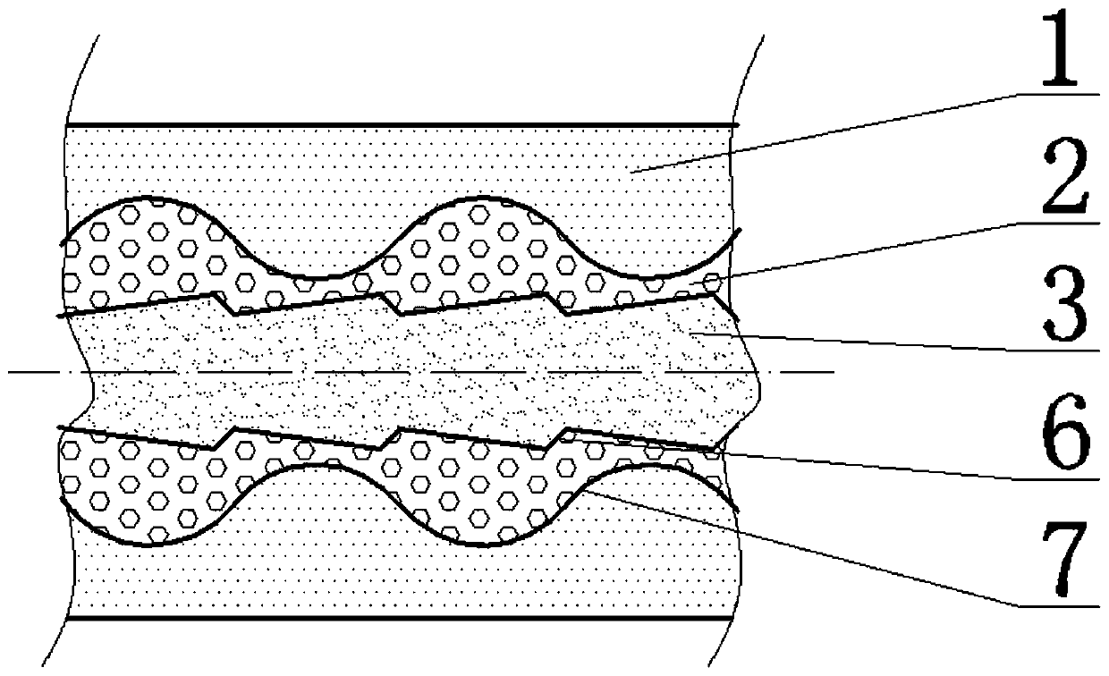
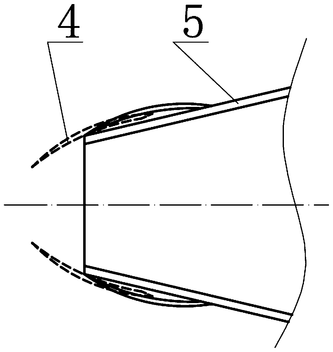
[0028] Such as figure 1 A visible light three-layer wave-lined colorful optical fiber is shown, the colorful optical fiber is composed of outer fluoromonomer methacrylate-2,2,2-trifluoroethyl ester polymer and bubble composite casing 1, the middle part The intermediate layer 2 composed of polymethyl methacrylate and glass slag particles and the inner aromatic polycarbonate core material 3, the longitudinal section of the casing 1 and the second layer 7 of the intermediate layer 2 is sinusoidal, and the sinusoidal wavelength is 20cm , the wave height is 0.3mm, the reference axis of the sine wave shape is parallel to the axis of the core material 3; the longitudinal section of the middle layer 2 and the first sub-layer 6 of the core material 3 is in a zigzag shape, and the dedendum connection lines corresponding to the dedendum between all teeth They are all parallel to the axis of the core material 3. The tooth surfaces of the sawtooth are divided into sunny slopes and shady sl...

Embodiment 2

[0045] The whole is consistent with Example 1, the difference is:

[0046] The longitudinal section of the shell 1 and the second layer 7 of the middle layer 2 is sinusoidal, with a sinusoidal wavelength of 24 cm and a wave height of 0.4 mm;

[0047] The longitudinal section of the first subdivision layer 6 is sawtooth-shaped, and the dedendum connection lines corresponding to the dedendum between all teeth are parallel to the axis of the core material 3. The tooth surfaces of the sawtooth are divided into sunny slopes and shady slopes, wherein The angle between the sunny slope surface and the line connecting the corresponding dedendum is 0.1°, the angle between the shady slope surface and the line connecting the corresponding dedendum is 1°, and the distance between adjacent dedendums is 10cm;

[0048] The outer diameter of the whole colorful optical fiber is 15mm;

[0049] The manufacturing method of the above-mentioned visible light three-layer wave-lined colorful optical ...


PUM

PropertyMeasurementUnit
particle diameteraaaaaaaaaa
refractive indexaaaaaaaaaa

Abstract

The invention discloses a visible light three-layer wave-lined colorful optical fiber and a manufacturing method thereof. The shell, the middle layer composed of polymethyl methacrylate and glass slag particles in the middle, and the inner aromatic polycarbonate core material, the longitudinal section of the shell and the second layer of the middle layer is sinusoidal; the middle layer and the core The longitudinal section of the first layer of the material is zigzag; when the optical fiber is applied, the light propagates in one direction from the junction of the shady slope surface and the tooth root to the junction of the sunny slope surface and the tooth root connection with a tooth shape. . The colorful optical fiber of the present invention is suitable for mixing light sources, does not require natural dispersion of filters, has dazzling and changeable colors, and can naturally change light with the displacement of the optical fiber.

Description

technical field [0001] The invention relates to the field of plastic optical fiber lighting, in particular to a visible light three-layer wave-lined colorful optical fiber and a manufacturing method thereof. Background technique [0002] In the prior art, the conductor of the optical fiber itself is mainly made of glass material (SiO2), and its transmission is to use light to pass through a medium with a high refractive index. Entering a medium with a low refractive index at an angle higher than the critical angle will produce The principle of total reflection allows light to maintain the characteristics of the light waveform for transmission in this medium. The core part of the high refractive index is the main channel for light transmission. The shell with a low refractive index covers the entire core. Since the core has a much higher refractive index than the shell, total reflection will occur, and light can therefore be transmitted in the core. The purpose of the prote...

Claims


Application Information

Patent Timeline
Patent Type & Authority Patents(China)
IPC IPC(8): G02B6/02G02B6/036B29C48/18
CPCB29C48/18G02B6/02033G02B6/02319G02B6/02342G02B6/036
Inventor 张敬敏
Owner STATE GRID SHANDONG ELECTRIC POWER CO WEISHAN POWER SUPPLY CO
Learn More