Piezoelectric element lead bonding method and piezoelectric element having pins

A piezoelectric element, lead welding technology, applied in the manufacture/assembly of electrical components, piezoelectric/electrostrictive devices, piezoelectric/electrostrictive/magnetostrictive devices, etc., can solve the problem of positive and negative electrodes of piezoelectric components Coating peeling off, welding process is difficult to strictly control, increase repair rate and other problems, to improve yield rate, improve heat dissipation effect, improve heat dissipation effect

Active Publication Date: 2019-08-16
苏州诺莱声科技有限公司
View PDF11 Cites 0 Cited by
  • Summary
  • Abstract
  • Description
  • Claims
  • Application Information

AI Technical Summary

Problems solved by technology

When welding the pins of the piezoelectric element, it is necessary to weld a pin on the two negative poles 1 and the positive pole 2 respectively. In the prior art, the pins are directly welded on the coating of the piezoelectric element, and direct welding will cause The problems are: 1. The heat generated by welding is likely to cause depolarization of the electroplated part of the piezoelectric element. 2. The heat generated by welding will also cause the positive and negative plating of the piezoelectric element to fall off. 3. The welding process is difficult to strictly control, resulting in Lower yield rate, increased repair rate

Method used


Image

  • Piezoelectric element lead bonding method and piezoelectric element having pins
  • Piezoelectric element lead bonding method and piezoelectric element having pins
  • Piezoelectric element lead bonding method and piezoelectric element having pins

Examples


Embodiment 1

[0048] This embodiment provides a piezoelectric element lead welding method, including the following steps:

[0049] S1: bonding a layer of conductive metal layer 9 to the surface of the positive and negative electrodes of the piezoelectric element through glue;

[0050] S2: welding pins on the conductive metal layer 9 corresponding to the positive and negative poles of the piezoelectric element;

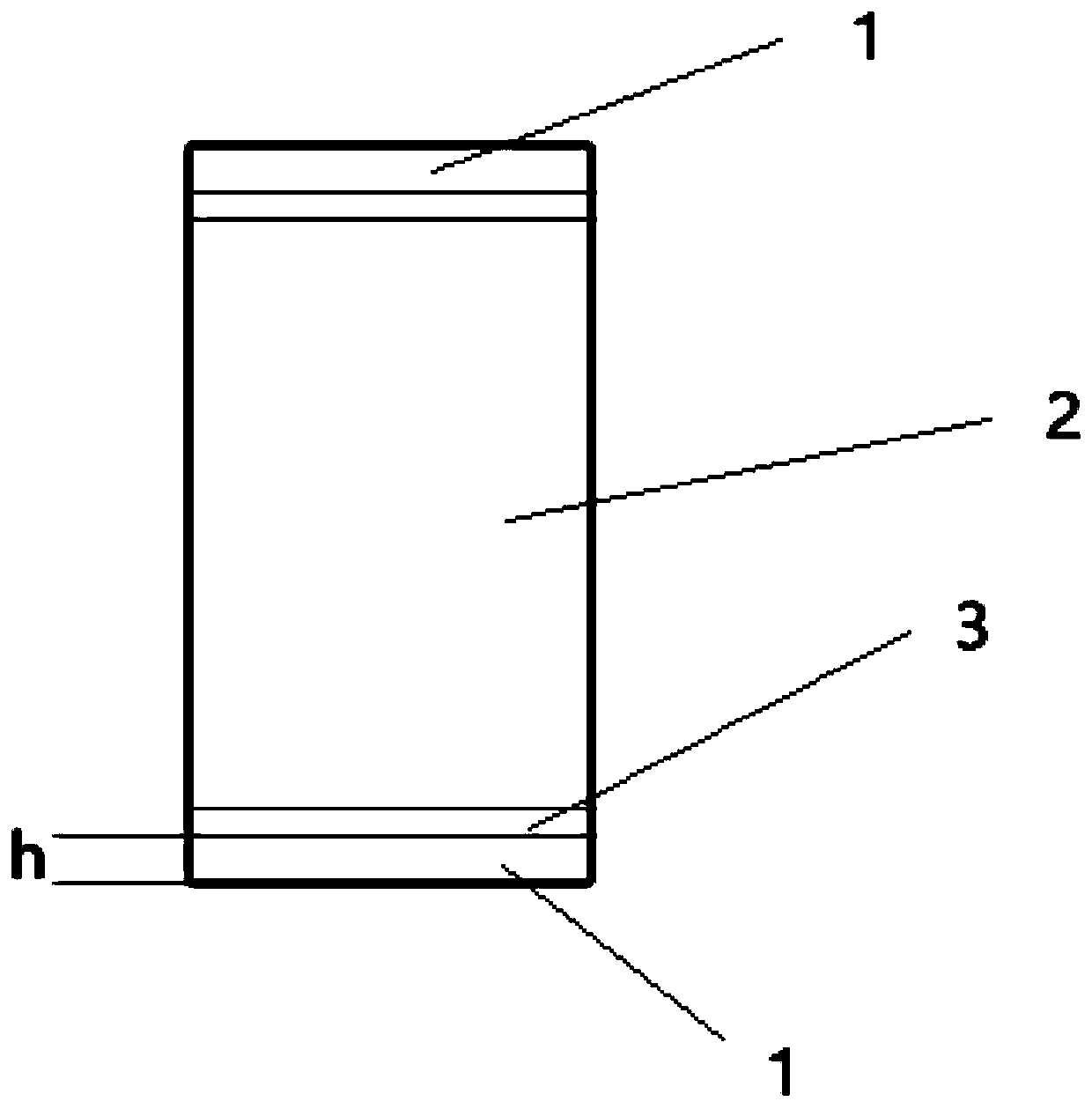
[0051] S3: Form a slit 6 along the isolation groove 3 of the piezoelectric element to cut the conductive metal layer 9 .

[0052] In the piezoelectric element lead welding method of the above-mentioned embodiments, the conductive metal layer 9 is bonded to the positive and negative surfaces of the piezoelectric element through conductive glue, and the pins are welded to the conductive metal layer 9. Since the pins are welded to the additional conductive On the metal layer 9, it is not directly welded with the coating of the piezoelectric element, which can prevent the coating from ...

Embodiment 2

[0057] This embodiment provides a piezoelectric element lead welding method, including the following steps:

[0058]S1: Bond a layer of conductive metal layer 9 on the surface of the positive and negative electrodes of the piezoelectric element through conductive glue. The conductive metal layer 9 has extensions beyond the piezoelectric element on both sides of the piezoelectric element, and on the extension Forming several folding lines 7 along the direction parallel to the two sides of the piezoelectric element, and folding the conductive metal layer 9 along the folding lines 7 to form a bending portion 8;

[0059] S2: welding pins on the conductive metal layer 9 corresponding to the positive and negative poles of the piezoelectric element;

[0060] S3: Form a slit 6 along the isolation groove 3 of the piezoelectric element to cut the conductive metal layer 9, and cut off the excess conductive metal layer 9 along both sides of the piezoelectric element.

[0061] In the meth...

Embodiment 3

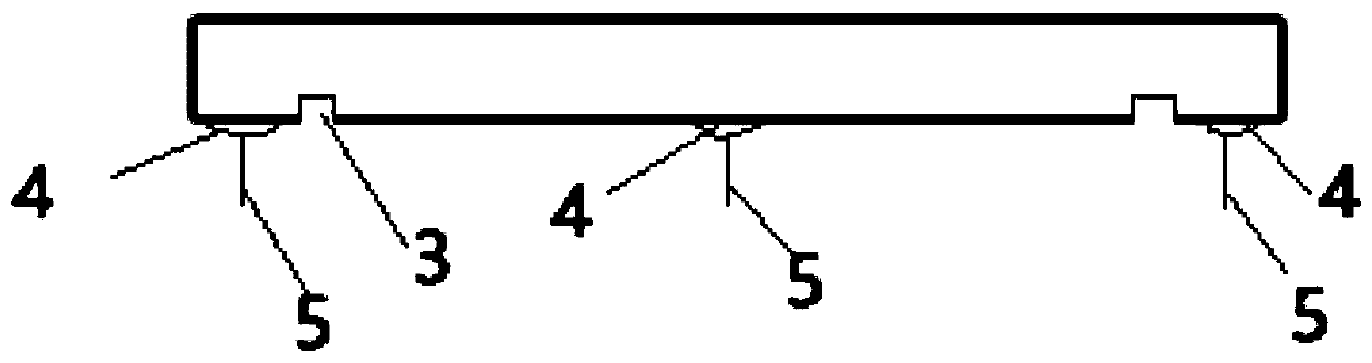
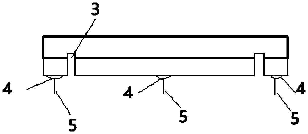
[0066] This embodiment provides a piezoelectric element with leads, which is obtained by welding the lead of the piezoelectric element in Embodiment 1 or 2. The structure of the piezoelectric element with pins such as image 3 As shown in or 4, the pin 5 is first connected to the conductive metal layer 9 through the solder joint 4, and the conductive metal layer 9 and the piezoelectric element are bonded into one body through conductive adhesive.


PUM


Abstract

The utility model relates to a piezoelectric element lead bonding method. A conductive metal layer is bonded at the surface of positive and negative poles of a piezoelectric element through glue, pinsare welded on the conductive metal layer, the pins are welded at the extra conductive metal layer and are directly welded with the coating of the piezoelectric element so as to avoid influences on the coating when welding is performed, the conductive metal layer can timely transfer heat generated by welding so as to improve the heat dissipation, besides, if welding faults are generated when welding is performed, after the pins and the conductive metal layer are removed, a new conductive metal layer is reused for repeated welding, and the piezoelectric element is not needed to be replaced, sothat the yields of product has been improved.

Description

technical field [0001] The application belongs to the technical field of piezoelectric element preparation, and in particular relates to a piezoelectric element lead wire welding method and a piezoelectric element with pins. Background technique [0002] The structure of piezoelectric elements (such as piezoelectric ceramics, piezoelectric single crystals, piezoelectric composites or piezoelectric polymers) used in ultrasonic transducers is as follows: figure 1 As shown in or 2, it includes the positive electrode 2 and the negative electrode 1 formed by separating the two sides through the isolation groove 3, and the entire piezoelectric element is plated with a conductive metal layer (usually a gold layer or a silver layer). When welding the pins of the piezoelectric element, one pin needs to be welded at the two negative poles 1 and the positive pole 2 respectively. In the prior art, the pins are directly welded on the coating of the piezoelectric element, and direct weldi...

Claims


Application Information

Patent Timeline
Patent Type & Authority Applications(China)
IPC IPC(8): H01L41/047H01L41/29
CPCH10N30/875H10N30/06
Inventor 周到冯星杰曹清源李智慧
Owner 苏州诺莱声科技有限公司
Why Eureka
Try Eureka