

Fuel cell cold start anode purging device and purging method
A technology of fuel cells and fuel cell stacks, applied in fuel cells, circuits, electrical components, etc., can solve problems such as hydrogen waste, achieve the effects of reducing operating costs, improving life, and ensuring stable output
- Summary
- Abstract
- Description
- Claims
- Application Information
AI Technical Summary
Problems solved by technology
Method used
Image

Examples
Embodiment 1
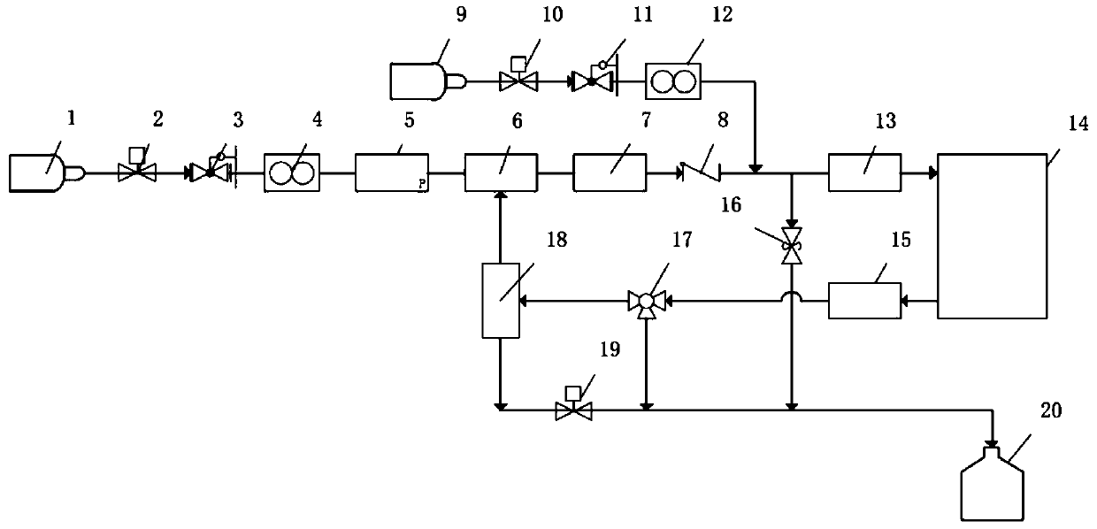
[0043] In a typical embodiment of the present invention, such as figure 1 As shown, a fuel cell cold-start anode purge device includes a nitrogen purge system connected to the hydrogen circulation system. The nitrogen purge system uses nitrogen purge. The system includes a nitrogen tank 9 and a second solenoid valve 10 connected in sequence. , the second decompression valve 11 , the second flow meter 12 , the second flow meter 12 is connected with the first integrated temperature, pressure and humidity sensor 13 in the hydrogen circulation system, and further connected with the inlet of the fuel cell stack 14 .
[0044] The nitrogen purge system also includes a second temperature-pressure-humidity integrated sensor 15 and a three-way valve 17, the second temperature-pressure-humidity integrated sensor 15 is connected to the inlet of the three-way valve 17, the three-way valve 17 is a three-way solenoid valve, and the three-way solenoid The inlet of the valve is connected to th...
Embodiment 2
[0052] A fuel cell cold-start anode purging method, using the fuel cell cold-start anode purging device described in Embodiment 1, comprising the following content:
[0053] When the fuel cell is shut down, it can immediately switch to the nitrogen purge system, the first solenoid valve in the hydrogen circulation system is closed, the second solenoid valve in the nitrogen purge system is opened, and the nitrogen purge system is turned on; The cooling water of the fuel cell heat dissipation system heats the fuel cell stack. When the temperature of the cooling water reaches the set value, the nitrogen purge system is turned on; after being released from the nitrogen tank, the nitrogen flows through the second solenoid valve and the second pressure reducing valve. , the second flow meter, the first temperature-pressure-humidity integrated sensor, the purged fuel cell stack, and the second temperature-pressure-humidity integrated sensor reach the three-way solenoid valve 17, and t...
PUM
 Abstract
Description
Claims
Application Information