Mixed current limiter based on clamping submodule and control method thereof

A current limiter and hybrid technology, applied in the field of power electronics, can solve the problems of high cost of hybrid DC current limiter, large loss of solid-state DC current limiter, large footprint, etc., to achieve flexible transfer and control capabilities Strong, saving investment effect

Inactive Publication Date: 2019-08-16
NORTH CHINA ELECTRIC POWER UNIV (BAODING)
View PDF6 Cites 1 Cited by
  • Summary
  • Abstract
  • Description
  • Claims
  • Application Information

AI Technical Summary

Problems solved by technology

[0004] In order to overcome the large loss and poor economy of the solid-state DC current limiter in the above-mentioned prior art and the high cost and large footprint of the hybrid DC current limiter, the present invention provides a hybrid fault current limiter based on clamp sub-modules And its control method, the hybrid fault current limiter based on the clamping sub-module includes a current branch, a current transfer branch and a current limiting branch

Method used


Image

  • Mixed current limiter based on clamping submodule and control method thereof
  • Mixed current limiter based on clamping submodule and control method thereof
  • Mixed current limiter based on clamping submodule and control method thereof

Examples


Embodiment 1

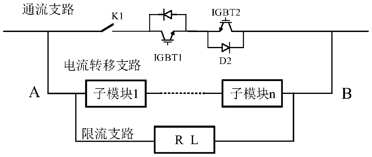
[0039] Embodiment 1 of the present invention provides a hybrid fault current limiter based on the clamping sub-module, which specifically includes a flow-through branch, a current transfer branch and a current-limiting branch. The functions of each branch are as follows:

[0040] The current-through branch is used to realize the conduction of the steady-state current of the DC line when the DC line is in normal operation, and transfer the fault current to the current-limiting branch after detecting a fault in the DC line;

[0041] Among them, the fault transfer branch is used to carry the fault current transferred by the flow-through branch, and force the current-limiting element in the current-limiting branch to connect to the DC line;

[0042] Among them, the current-limiting branch is used to increase the system damping and reduce the rising speed of the fault current after being connected in series with the DC line.

[0043] The flow-through branch above includes a fast is...

Embodiment 2

[0050] Embodiment 2 of the present invention provides a control method for a hybrid current limiter based on a clamp sub-module, and the specific process is as follows:

[0051] When the DC line where the hybrid current limiter based on the clamping sub-module is located is in normal operation, the IGBTs in the current transfer branch are all locked, the current limiting branch is out of operation, the IGBT1 and IGBT2 in the current passing branch are turned on, and the steady-state current Or the fault current flows through the flow-through branch, and the schematic diagram of the steady-state current flow path when the DC line is in normal operation is shown in Figure 4 shown.

Embodiment 3

[0053] The control method of the secondary commutation type DC current limiter provided in Embodiment 3 of the present invention, the specific process is as follows:

[0054] Before detecting a fault on the DC line where the hybrid current limiter based on the clamp sub-module is located, IGBT1 and IGBT2 in the current branch are turned on, and the steady-state current or fault current flows through the current branch. Before the fault is detected The schematic diagram of the flow path of the DC line fault current is as follows: Figure 5 shown.


PUM


Abstract

The invention provides a mixed current limiter based on a clamping submodule and a control method thereof. The mixed current limiter comprises a through-flow branch and a current limiting branch, adopts a full-control device, and is simple in logic and high in controllability; and the current limiter clamping submodule topology has a plurality of alternative topologies. The motion process of the current limiter does not depend on the protection effect of a lightning arrester so that the service life of the current limiter is effectively prolonged. The control method of the mixed current limiter based on the clamping submodule controls the mixed current limiter based on the clamping submodule through two conditions of normal operation of the direct-current line where the current limiter islocated or prior to detection of the faults of the direct-current line where the current limiter is located and after detection of the faults of the direct-current line where the current limiter is located based on the clamping submodule.

Description

technical field [0001] The invention relates to the technical field of power electronics, in particular to a hybrid fault current limiter based on a clamp sub-module and a control method thereof. Background technique [0002] Due to its unique advantages in technology and economy, high voltage direct current (HVDC) has been widely used in long-distance large-capacity power transmission and regional networking in China. HVDC transmission not only has many characteristics such as grid stability and reliability, but also facilitates the large-scale access of distributed energy. However, due to the inability to take good countermeasures when the system fails, the development of the DC power grid is limited. The main technical difficulty lies in the immature technology of high-voltage and large-capacity DC current limiters. Therefore, research on a device that can limit the rapid rise of DC current and reduce the pressure on all levels of equipment in the DC system when the DC ...

Claims


Application Information

Patent Timeline
Patent Type & Authority Applications(China)
IPC IPC(8): H02H9/02H02J3/36
CPCH02H9/02H02H9/025H02J3/36Y02E60/60
Inventor 赵成勇宋冰倩赵西贝许建中
Owner NORTH CHINA ELECTRIC POWER UNIV (BAODING)
Why Eureka
Try Eureka