
LC resonant charging power supply and electromagnetic protection method thereof

A technology of resonant charging and electromagnetic protection, which is applied to battery circuit devices, current collectors, electric vehicles, etc., and can solve problems such as energy leakage, damage and disorder of pulse transformers and other components

Active Publication Date: 2019-08-16
湖南华成迈创电子科技有限公司
View PDF1 Cites 0 Cited by
  • Summary
  • Abstract
  • Description
  • Claims
  • Application Information

AI Technical Summary

Problems solved by technology

[0003] Electromagnetic interference is mainly aimed at the control part of the charging power supply. Since the center frequency of the switch electromagnetic radiation is usually around 20MHz and has a wide frequency bandwidth, the resonant charging power supply system is also It is unavoidable to have a circuit connection. Conventional methods, such as transformer isolation, optical fiber isolation, metal shell shielding and lithium battery power supply, etc., have certain effects, but still cannot completely shield electromagnetic interference, causing the trigger control module of the LC resonant power supply to often It is falsely triggered by interference, so that when the next work control switch, such as thyristor switch, Mos tube, etc., cannot work according to the set timing, and then the entire charging system cannot operate; at the same time, due to the disorder of the working sequence, the energy stored in the system during work Abnormal discharge, causing abnormal damage to the entire thyristor switch, control circuit board, pulse transformer and other components

Method used

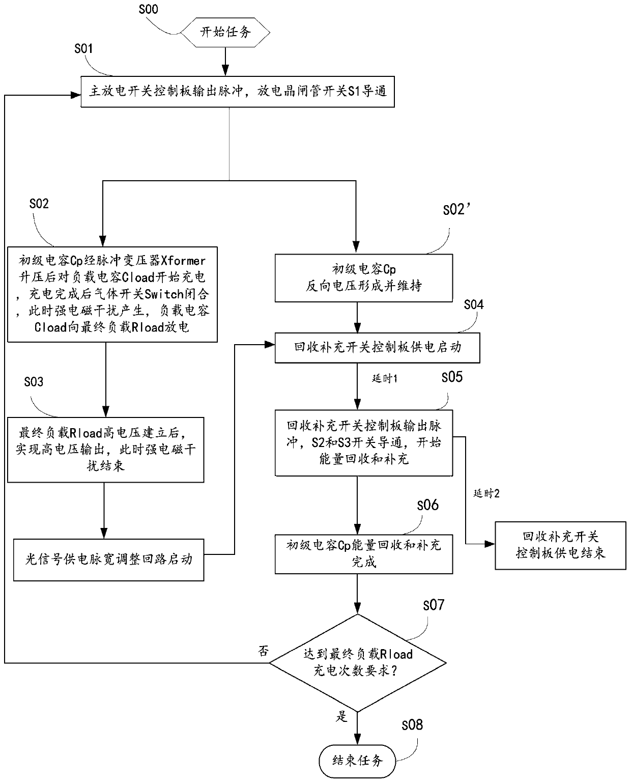
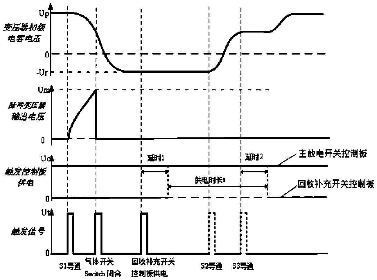

Image

  • LC resonant charging power supply and electromagnetic protection method thereof
  • LC resonant charging power supply and electromagnetic protection method thereof
  • LC resonant charging power supply and electromagnetic protection method thereof

Examples


Embodiment Construction

[0031] It should be noted that, in the case of no conflict, the embodiments of the present invention and the features in the embodiments can be combined with each other. The present invention will be described in detail below with reference to the accompanying drawings and examples.

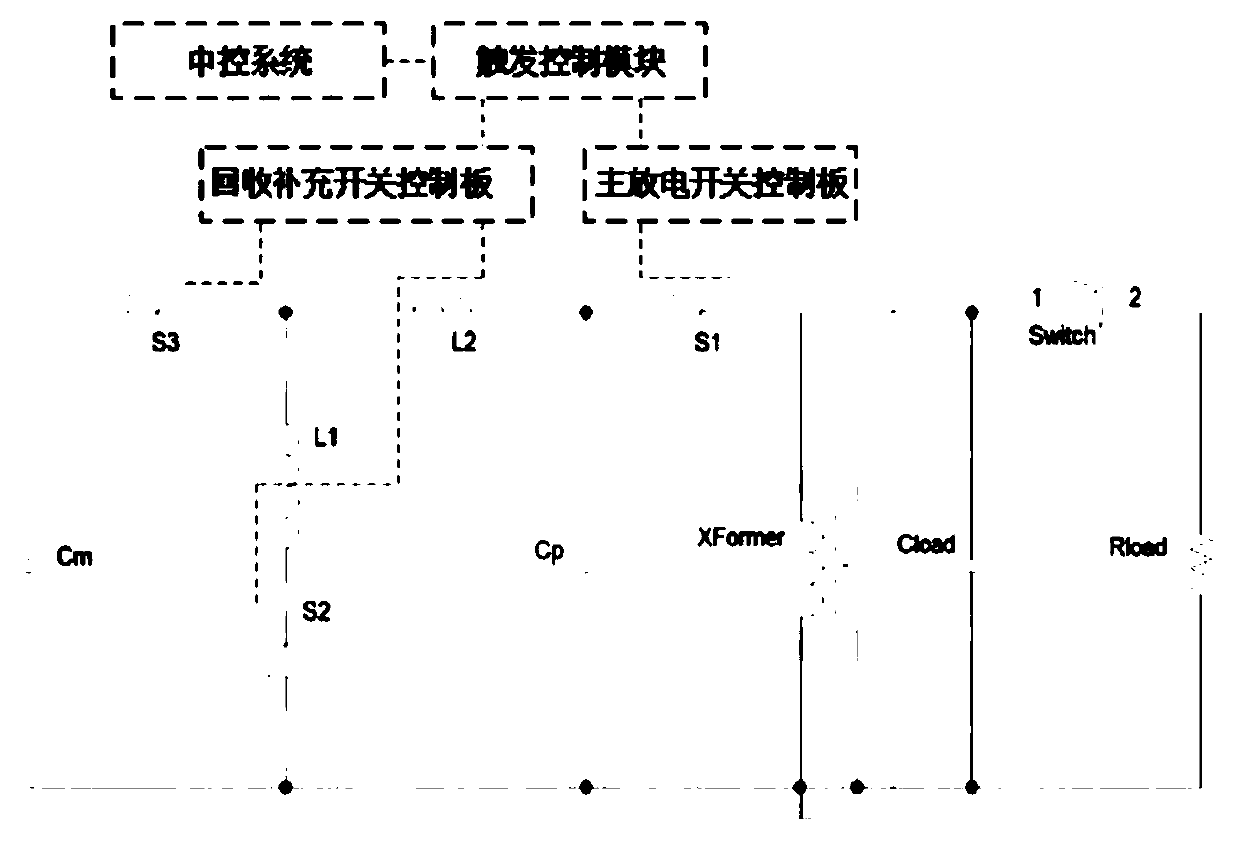
[0032] Such as figure 1 As shown, an LC resonant charging power supply of the present invention includes a resonant charging circuit and a load circuit: the resonant charging circuit includes a central control system, a trigger control module, a main discharge switch control board, a recovery supplementary switch control board, a primary capacitor Cp, and a discharge thyristor Switch S1, energy recovery thyristor switch S2, protection inductor L1, resonant charging inductor L2, pulse transformer Xformer, energy replenishment thyristor switch S3 and energy storage capacitor Cm, wherein the central control system is connected to the trigger control module; the trigger control module passes through ...


PUM


Abstract

The invention discloses an LC resonant charging power supply and an electromagnetic protection method thereof. An energy recovery thyristor switch S2 and an energy supplement thyristor switch S3 are powered by a recovery supplement switch control board, and a discharge thyristor switch S1 is powered by a main discharge switch control board. Before the charging of a resonant power supply, the recovery supplement switch control board is in an unpowered state, after a discharge switch works, a designed optical light is used for a power supply pulse width adjustment circuit to select given power supply time and power supply pulse width, a trigger control module is powered, the time-sharing operation of a trigger control panel is achieved, therefore, the time-sharing operation of the energy recovery switch and the energy supplement switch is achieved, and the electromagnetic compatibility and operational reliability of the charging power supply in a strong electromagnetic environment are improved.

Description

technical field [0001] The invention belongs to the technical field of high-power charging power supply devices, and in particular relates to an LC resonant charging power supply and an electromagnetic protection method thereof. Background technique [0002] High-power LC resonant charging power supply has the advantages of compact structure, repeatable frequency operation, and high charging power. It has been widely used in high-current electron accelerators, pulse power modulators, high-power lasers, and high-power microwaves. In recent years, the requirements for output power, energy, and repetition frequency of high-current electron accelerators, pulse modulators and other devices have been continuously improved, and higher requirements have been put forward for charging power supplies. Due to the load of the charging power supply, such as Marx generators, pulse forming lines, high-voltage capacitors, etc., it is necessary to use a high-power discharge gas switch during ...

Claims


Application Information

Patent Timeline
IPC IPC(8): H02J7/00H02M3/137H02M1/44
CPCH02M3/137H02M1/44H02J7/00Y02B70/10
Inventor 殷毅李志强王弘刚洪志强
Owner 湖南华成迈创电子科技有限公司
Learn More