Supercharge Your Innovation With Domain-Expert AI Agents!

Control device and system of laser cutting gas path

A gas circuit control and laser cutting technology, applied in laser welding equipment, manufacturing tools, welding equipment, etc., can solve the problems of poor laser cutting process reliability, damage to the fiber of the laser generator, bursting of the gas pipeline, etc., to avoid problems such as The effect of pipeline bursting, improving the degree of purity and ensuring stability

Pending Publication Date: 2019-08-20
JINAN BODOR LASER CO LTD
View PDF0 Cites 1 Cited by
  • Summary
  • Abstract
  • Description
  • Claims
  • Application Information

AI Technical Summary

Problems solved by technology

[0003] In the prior art laser cutting gas circuit, affected by gas cleanliness, analog voltage, numerical control system control, etc., there is a problem of air pressure fluctuations. When the gas pressure is too high, it is easy to cause the gas pipeline to burst. When the cutting gas pressure is too low or When the gas contains impurities, it is easy to cause damage to the optical lens inside the cutting head. In severe cases, it may even cause damage to the optical fiber of the laser generator, and the processed workpiece is scrapped, resulting in poor reliability of the laser cutting process.

Method used


Image

  • Control device and system of laser cutting gas path
  • Control device and system of laser cutting gas path
  • Control device and system of laser cutting gas path

Examples


Embodiment 1

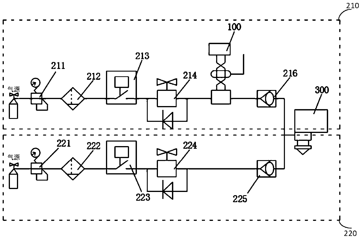
[0044] figure 1 It is a schematic diagram of a gas path control device for laser cutting provided by Embodiment 1 of the present invention.

[0045] refer to figure 1 , the laser cutting gas circuit control device mainly includes a control system 100 , at least one gas pipeline and a cutting head input port 300 . The control system can adopt CNC control system or board control system.

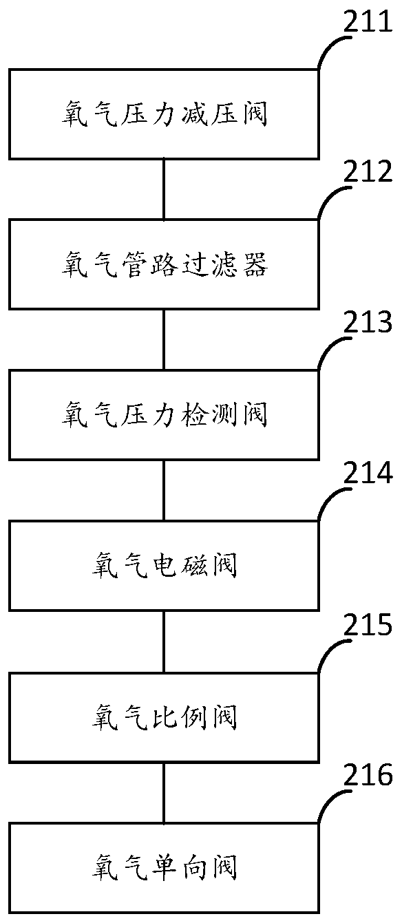
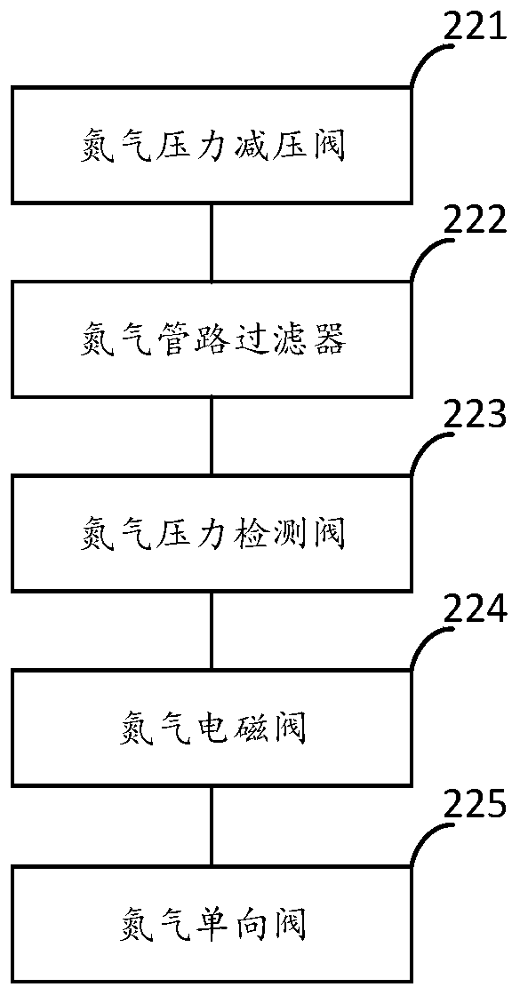
[0046] Further, each gas pipeline includes a gas pressure reducing valve, a pipeline filter, a pressure detection valve, a solenoid valve and a one-way valve connected in sequence; wherein, the pressure detection valve and the solenoid valve in each gas pipeline All are connected with the control system; the one-way valve of each gas pipeline is connected with the input port 300 of the cutting head.

[0047] In this embodiment, two gas pipelines will be taken as an example for illustrative description. Wherein, the first gas pipeline is an oxygen pipeline 210 , and the second gas pipeline i...

Embodiment 2

[0085] Figure 4 It is a schematic diagram of a gas path control system for laser cutting provided by Embodiment 2 of the present invention.

[0086] refer to Figure 4 , the gas path control system for laser cutting includes the gas path control device for laser cutting as in the first embodiment above, and also includes a plate 400 .

[0087] The plate 400 is arranged below the input port 300 of the cutting head in the gas circuit control device for laser cutting. During processing, the cutting head input port 300 and the plate 400 keep a certain distance between the cutting head input port 300 and the cutting plate 400 according to the processing technology requirements. The distance in this embodiment is within the range of 0.3mm-15mm. The required gas supply is provided directly to the processing of the plate 400 .

[0088] A gas circuit control system for laser cutting provided by the above-mentioned embodiments of the present invention includes a control system, at l...


PUM


Abstract

The invention provides a control device and system of a laser cutting gas path, and relates to the technical field of laser cutting. The device comprises the control system, at least one gas pipelineand a cutting head input opening. Each gas pipeline comprises a gas pressure reducing valve, a pipeline filter, a pressure detection valve, a solenoid valve and a one-way valve, all of which are connected in sequence. The pressure detection valve and the solenoid valve in each gas pipeline are connected with the control system. The one-way valve of each gas pipeline is connected with the cutting head input opening. The purity of gas in the gas path can be improved, the gas pressure stability can be improved, and then the laser cutting processing technology can be improved.

Description

technical field [0001] The invention relates to the technical field of laser cutting, in particular to a laser cutting gas path control device and system. Background technique [0002] During the cutting process of laser equipment, gas path factors have a key influence on the cutting effect, and directly determine whether the cutting workpiece meets the processing standards. [0003] In the prior art laser cutting gas circuit, affected by gas cleanliness, analog voltage, numerical control system control, etc., there is a problem of air pressure fluctuations. When the gas pressure is too high, it is easy to cause the gas pipeline to burst. When the cutting gas pressure is too low or When the gas contains impurities, it is easy to cause damage to the optical lens inside the cutting head. In severe cases, it even causes damage to the optical fiber of the laser generator, and the processed workpiece is scrapped, resulting in poor reliability of the laser cutting process. Conte...

Claims


Application Information

Patent Timeline
IPC IPC(8): B23K26/14B23K26/38B23K26/70
CPCB23K26/14B23K26/38B23K26/702
Inventor 孔文一张红雨郑元强
Owner JINAN BODOR LASER CO LTD
Features
  • R&D
  • Intellectual Property
  • Life Sciences
  • Materials
  • Tech Scout
  • Unparalleled Data Quality
  • Higher Quality Content
  • 60% Fewer Hallucinations
Learn More