Driving face temporary support equipment and working method thereof

A technology for excavation work and equipment, applied in the direction of temporary shield, mining equipment, shaft equipment, etc., can solve the problems of long time, large labor demand, cumbersome process, etc., and achieve the effect of improving productivity, reducing labor, and good flexibility

Active Publication Date: 2019-08-20
SHANDONG UNIV OF SCI & TECH
View PDF5 Cites 7 Cited by
  • Summary
  • Abstract
  • Description
  • Claims
  • Application Information

AI Technical Summary

Problems solved by technology

This kind of temporary support method is cumbersome in process, requires a large labor force, takes a long time, and has empty top work

Method used


Image

  • Driving face temporary support equipment and working method thereof
  • Driving face temporary support equipment and working method thereof
  • Driving face temporary support equipment and working method thereof

Examples


Embodiment 1

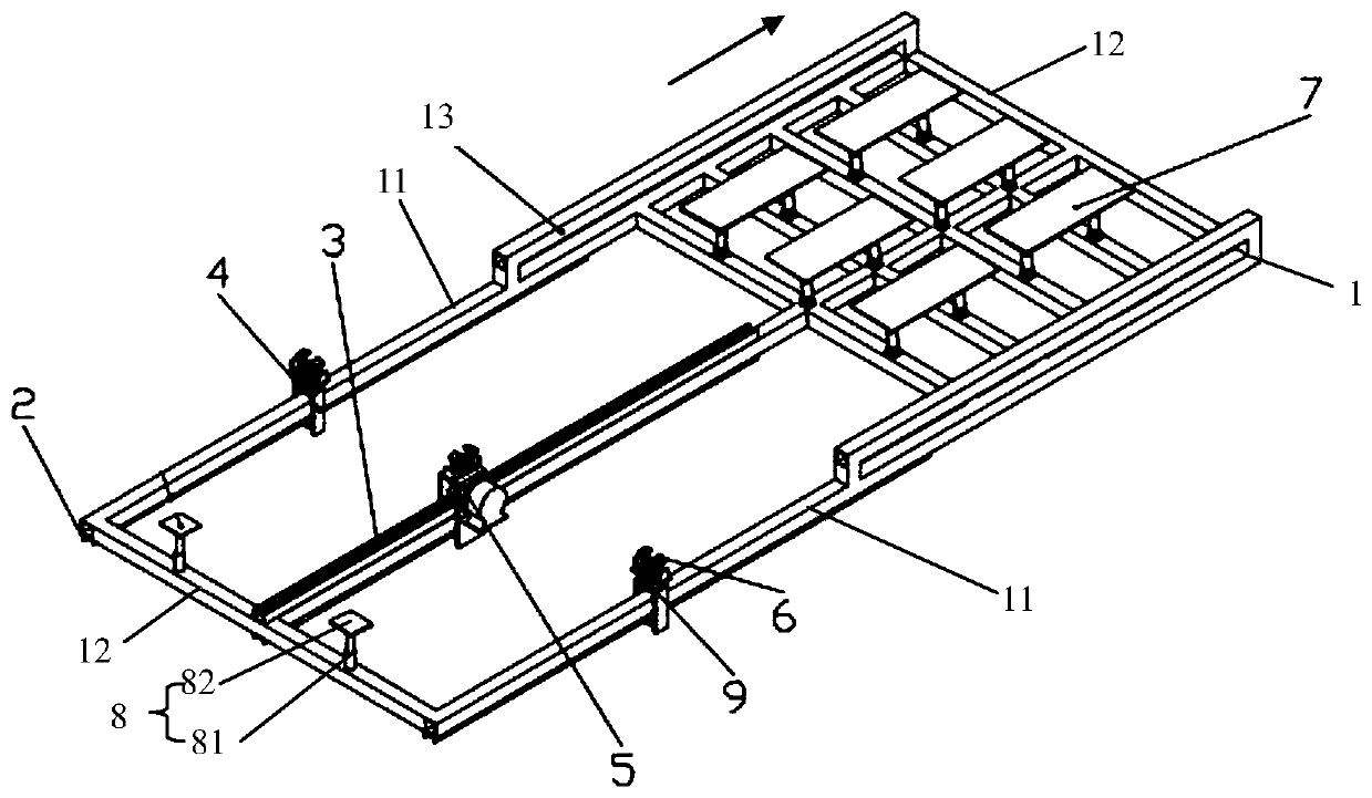
[0044] A kind of temporary support equipment for excavation work, such as Figure 1-6 As shown, it includes a front beam frame 1, which includes three square steel pipes 11 along the roadway direction and a connecting rod 12 for connecting the three square steel pipes 11 and perpendicular to the roadway direction. The front end of the front probe beam frame 1 is provided with at least Four sets of connecting rods, and one set of connecting rods at the rear end;

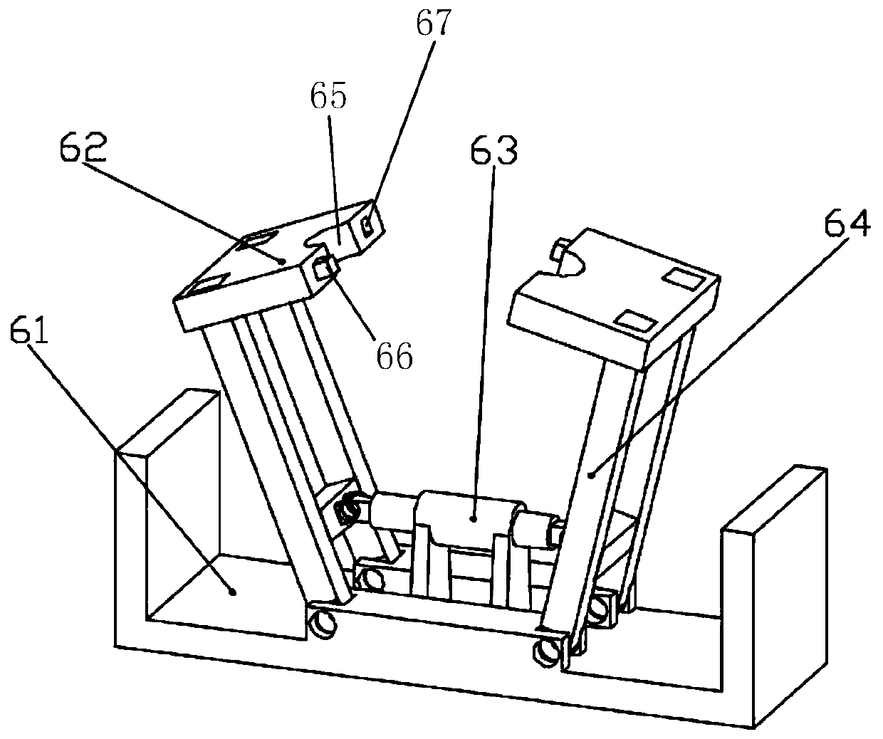
[0045] Three square steel pipes 11 are evenly arranged along the roadway width, the middle square steel pipe is provided with a drive mechanism 5, the square steel pipes 11 on both sides are provided with a guide mechanism 4, and the upper part of the drive mechanism 5 is fixedly provided with a clamping device 6 and a guide mechanism 4 The upper part is also equipped with a clamping mechanism 6 through the landing gear 9, and the clamping mechanism 6 is used to clamp the existing anchor rod in the roadway;

[0046] ...

Embodiment 2

[0048] A kind of excavation work face temporary support equipment, its structure is as shown in embodiment 1, the difference is, as shown in Figure 5, the quantity of lifting platform 7 is 6, and lifting platform 7 comprises two lifting hydraulic cylinders 71 and The lifting top plate 72 located on the upper part of the two lifting hydraulic cylinders 71 and the lifting hydraulic cylinder 71 of the lifting platform can keep synchronous elongation, and the elongation can also be adjusted according to the complex situation of the roadway. The bottom of the lifting hydraulic cylinder 71 is fixed on the connecting rod 12 , the top of the extension rod of the lifting hydraulic cylinder 71 is connected with the lifting roof 72 through a multi-degree-of-freedom connector 73 to ensure that the lifting roof 72 is self-adjusting to adapt to the complex shape of the roadway top. The multi-degree-of-freedom connector 73 here is a connector composed of a pair of ordinary hinges with a relat...

Embodiment 3

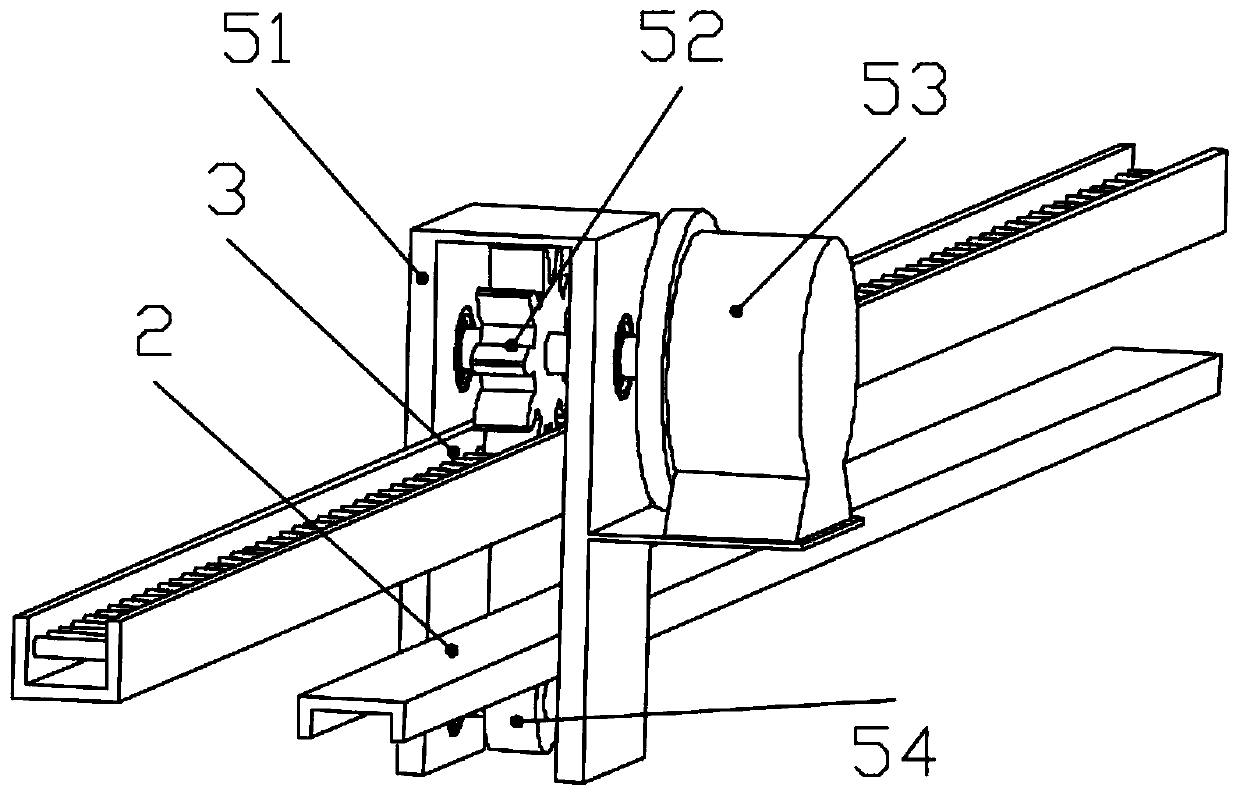
[0052] A kind of temporary support equipment for excavation work, its structure is as shown in embodiment 2, the difference is, as figure 1 , 2 As shown, the bottoms of the three square steel pipes without connecting rods are fixedly provided with an inverted U-shaped guide rail 2, as the walking track of the guide mechanism 4 and the drive mechanism 5, and a pin rail 3 is fixedly installed above the square steel pipe in the middle position. Used to cooperate with the drive gear 52 inside the drive mechanism;

[0053] Such as figure 2 As shown, the drive mechanism 5 includes a drive box body 51, a drive gear 52 cooperating with the pin track 3 is installed on the top of the drive box body 51, a motor 53 is arranged on the outside of the drive box body 51, and the output shaft of the motor 53 is connected to the drive gear 52. connected to drive the drive gear 52 to rotate, thereby realizing the relative movement between the pin rail 3 and the drive gear 52;

[0054] The dr...


PUM


Abstract

The invention discloses driving face temporary support equipment and a working method thereof, and belongs to the field of roadway support. The equipment comprises a front beam frame; the front beam frame comprises three square steel pipes, and connecting rods for connecting the three square steel pipes; at least four sets of connecting rods are arranged at the front end of the front beam frame, and a set of connecting rods is arranged at the back end; a driving mechanism is arranged on the square steel pipe in middle; guide mechanisms are arranged on the square steel pipes on two sides; a clamping device is fixedly arranged at the upper part of the driving mechanism; clamping mechanisms are mounted at the upper parts of the guide mechanisms through undercarriages; multiple sets of liftingplatforms are uniformly arranged on the four sets of connecting rods at the front end of the front beam frame; projection brackets are arranged at the front ends of the square steel pipes on two sides; and a tail leveling device is arranged at the back end of the front beam frame. The anchor net and steel strip pavement and the temporary support work are once realized to effectively prevent the operation of workers under empty tops; and the autonomous movement of the temporary support equipment is realized to achieve important significance on improvement of the support efficiency and reduction of the manpower and the labor intensity.

Description

technical field [0001] The invention relates to a temporary support device for a tunneling working face and a working method thereof, belonging to the technical field of roadway support. Background technique [0002] During the roadway excavation process, the supporting work of the underground roadway is the top priority for safe production. Temporary support refers to the support erected to prevent the roof from falling before the permanent support is erected, and its purpose is to protect the safety of construction personnel. At present, the temporary support of coal mines is mostly supported by the front beam support. The roadheader cuts and exits. The construction personnel carry the anchor net and steel belt, and lift them to the top of the roadway, and then the front beam moves forward to support the anchor net and steel belt. , and then use solid wood to reinforce, and then carry out the operation of bolting, and finally the front beam is moved back, and the roadhead...

Claims


Application Information

Patent Timeline
Patent Type & Authority Applications(China)
IPC IPC(8): E21D19/00E21D20/00E21D11/14E21D11/40
CPCE21D11/14E21D11/40E21D19/00E21D20/00
Inventor 张鑫于尚鑫曾庆良谢道祥宋克楠李旭王通马德建葛红恩
Owner SHANDONG UNIV OF SCI & TECH
Why Eureka
Try Eureka