[0027] The present invention will be further described in detail below in conjunction with the drawings and specific embodiments.
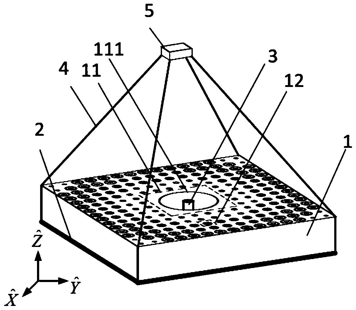
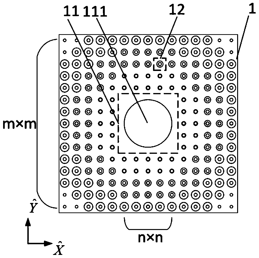
[0028] Reference figure 1 The present invention includes a reflecting mirror composed of a square mixed medium plate 1 and a metal flat plate 2 pasted on the lower surface of the square mixed medium plate 1, a monopole antenna unit 3, a bracket 4, and a rectangular waveguide 5.
[0029] In this embodiment, the operating frequency of the monopole antenna unit 3 is 16GHz, the operating length is 4.6875mm, the bracket 4 uses four rigid materials, and the rectangular waveguide 5 uses an internal cross-section width of 15.8mm and a height of 7.9mm. Standard WR62 waveguide with transmission frequency range from 11.9GHz to 18.0GHz.
[0030] In this embodiment, the axis of the monopole antenna unit 3 and the axis of the cavity of the rectangular waveguide 5 are all coincident with the center normal of the square mixed dielectric plate 1, and the ends of the four rigid materials of the bracket 4 are respectively connected to the rectangular waveguide 5 The four vertices of the outer frame of the output port and the four vertices of the upper surface of the square mixed media plate 1. The metal flat plate 2 is located on the xOy plane in the spatial rectangular coordinate system. The center normal of the square mixed medium plate 1 is parallel to the z axis.
[0031] Reference figure 2 In this embodiment, the square mixed medium plate 1 includes a medium plate 11 located in the center and a ring-shaped array composed of a plurality of mixed medium units 12 spliced with the medium plate 11, and the center of the medium plate 11 is provided with The first cylindrical via 111, the annular array is an area array composed of m×m periodically arranged mixed media units 12 minus n×n periodically arranged mixed media units at the center of the area array 12 constitution, mn≥2, n≥2.
[0032] In this embodiment, the medium used by the dielectric unit is Rogers RT/duroid 5880, the relative dielectric constant is 2.2, the loss tangent is 0.001, and the square shape of the mixed dielectric plate 1 is 90×90×15 mm, that is, the dielectric material The thickness T=15mm, m=15, n=5, the outer dimension of the dielectric plate 11 in the center is 30×30×15mm, the radius of the first cylindrical through hole 111 is 12mm, and its axis is aligned with the center of the square mixed medium plate 1. The normals coincide.
[0033] Reference image 3 The mixed media unit 12 is composed of a second cylindrical through hole 121 and a metal wire 122 loaded therein. The cross section of the metal wire 122 is circular. In each mixed media unit 12, the second cylindrical through hole 121 The axis of each mixed media unit 12 coincides with the axis of the metal wire 122 loaded therein, and the axes of the cylindrical through holes 121 are parallel to each other and coincide with the axis of the first cylindrical through hole 111. The mixed media unit 12 is in The physical structure in each direction is different, the phase gradient change in the z direction can be constructed, and the refractive index characteristics of near zero in the x and y directions can be constructed.
[0034] In this embodiment, considering the actual processing accuracy limitation, from the axis of the first cylindrical through hole 111 to the edge of the square mixed medium plate 1, the second cylindrical shape of the mixed medium unit 12 is circularly distributed every two to three circles. The radius of the via 121 is the same. On the four corners of the square mixed media, there are 3 metal wires 122 in each corner, and 12 metal wires 122 have the same radius, which reduces the requirement of processing accuracy. The overall size of the mixed media unit is 6× 6×15mm, that is, side length b=6mm, thickness T=15mm, radius R of the second cylindrical via 121 i Divide into three groups from the center to the edge, namely R 1 =1mm, R 2 =1.6mm, R 3 =2.2mm, the radius r of the metal wire 122 i Divided into two groups, the 12 metal wires 122 on the four corners of the square mixed medium have a radius r 1 =0.7mm, the radius r of other metal wires 122 2 = 0.8mm.
[0035] Reference Figure 4 , The spherical wave emitted by the feed source at the focal point has its isophase surface as a spherical surface, and the directional wave radiation is reflected by the reflector, and its isophase surface is a quasi-plane. The second cylindrical via 121 has a radius R i The position of the second cylindrical through hole 121 in the mixed media plate 11 is determined, and it is not affected by the radius r of the metal wire 122. i The specific calculation formula is as follows:
[0036]
[0037] Where f is the focal length of the reflector, c is the speed of light in vacuum, f is the operating frequency, T is the thickness of the square mixed medium plate, and d is the distance from the axis of the second cylindrical via to the center normal of the square mixed medium plate , B is the side length of the mixed media unit, ε r Use the dielectric constant of the medium for the mixed medium unit.
[0038] In this embodiment, the focal length of the mirror is f=75mm, and the working frequency is f=16GHz.
[0039] The radius of the wire 113 is r i The calculation formula is:
[0040]
[0041] Where ε eff It is the equivalent dielectric constant in the radial direction of the mixed media unit, and its value is close to 0, and its value is related to the structure of the metal wire. c is the speed of light in vacuum, f is the working frequency, ε r The dielectric constant of the medium used for the mixed medium unit, R i Is the radius of the second cylindrical via at the metal wire loading position, b is the side length of the mixed media unit, and r i <
[0042] In this embodiment, the operating frequency f=16GHz.
[0043] Reference Figure 5 , The square mixed medium plate 1 exhibits near-zero refractive index characteristics in the radial direction. The monopole antenna unit 3 radiates spherical waves before transmission, and uses the wavefront shaping effect of the near-zero refractive index material. After transmission, the square mixed medium plate The four edges of 1 form four directional beams perpendicular to the side plane of the square mixed medium plate 1, and the isophase plane after transmission is a quasi-plane.
[0044] The following describes the technical effects of the present invention in combination with simulation experiments:
[0045] 1. Simulation conditions and content:
[0046] Simulation conditions: 3D full-wave electromagnetic field simulation software CST Microwave Studio2017 electromagnetic simulation software.
[0047] Simulation content: 1. A mixed dielectric antenna that realizes axial directional beam and radial multi-beam radiation. The comparison of the far-field and near-field electric fields of the loaded and unloaded metal wires when radiating along the axial direction. The simulation results are shown in Figure 6 and Figure 7 Shown
[0048] 2. A comparison diagram of the radiated far-field and near-field electric fields of a mixed dielectric antenna that achieves axial directional beam and radial multi-beam radiation. The simulation results are as follows Figure 8 with Picture 9 Shown.
[0049] 3. Analysis of simulation results:
[0050] Reference Image 6 , Image 6 It is a comparison diagram of the far-field radiation of the loaded and unloaded metal wires when radiating along the axial direction in the embodiment of the present invention, Image 6 The solid line represents the far-field schematic diagram of the metal wire loaded by the mixed dielectric unit. In the yOz plane in the Cartesian coordinate system, the gain varies with theta angle, the maximum radiation direction of the antenna is 0°, the gain is 16.64dBi, and the half-power beam width is 11.7 °; Figure 5 The dashed line represents the far-field schematic diagram of the mixed media unit without metal wire. In the yOz plane of the Cartesian coordinate system, the gain varies with theta angle, the maximum radiation direction is 0°, the gain is 16.56dBi, and the half-power beam width is 12.2° . The simulation results show that the present invention does not have too much influence on the far field of the axial radiation when the loaded and unloaded metal wires are spoken along the axial direction.
[0051] Reference Figure 7 , Figure 7 It is a schematic diagram of the normalized near-field electric field of the radiation of the loaded and unloaded metal wires when radiating along the axial direction in the embodiment of the present invention, Figure 7 (a) is a schematic diagram of the normalized near-field electric field of the radiation loaded with the metal wire when radiating along the axial direction in the embodiment of the present invention, Figure 7 (b) is a schematic diagram of the normalized near-field electric field of radiation that is not loaded with metal wires when radiating along the axial direction in the embodiment of the present invention. Figure 7 (a) and Figure 7 (b) The electromagnetic wave radiated in the axial direction, the spherical wave radiated from the rectangular waveguide of the feed, after the reflection of the metal plate, both obtain the plane wave front in the axial direction. The simulation results show that the invention loads when radiating in the axial direction. And the unloaded metal wire structure has almost no effect on the near-field electric field of its axial radiation.
[0052] Reference Figure 8 , Figure 7 This is the schematic diagram of the far field of radial radiation when the monopole antenna unit is excited in this embodiment. The solid line represents the far field diagram of the radial radiation when the monopole antenna is excited. In the xOy plane of the Cartesian coordinate system, the gain With the change of phi angle, there are four maximum radiation directions, respectively 0°, 90°, 180°, 270°, gain of 6.75dBi, half-power beam width of 15.5°, the simulation result shows that the present invention can produce radial Multi-beam directional radiation.
[0053] Reference Picture 9 , Picture 9 This is the normalized near-field electric field diagram of the radial radiation when the monopole antenna unit is excited in this embodiment. In the figure, the incident wave radiated from the monopole antenna unit passes through the radial wavefront shaping effect of the square mixed dielectric plate, and The outer shape of the square mixed medium plate is square, so after transmission, four quasi-planar wavefronts are obtained in the four propagation directions. The simulation result shows that the present invention can generate radial multi-beam directional radiation.