Liquid non-submerged impinging stream reaction device and reaction method

A technology of impinging flow reaction and reaction device, which is applied in chemical/physical/physical-chemical nozzle reactors, chemical instruments and methods, hydrocarbon oil cracking, etc., and can solve problems such as insufficient strengthening effect of new substances.

Active Publication Date: 2019-08-23
捷创(东营)能源技术有限责任公司 +1
View PDF10 Cites 3 Cited by
  • Summary
  • Abstract
  • Description
  • Claims
  • Application Information

AI Technical Summary

Problems solved by technology

[0006] The main purpose of the present invention is to provide a liquid non-submerged impinging flow reaction device and reaction method to solve the problem of insufficient strengthening effect of submerged impinging flow in destroying the internal energy of molecular structure and promoting the production of new substances in the prior art question

Method used


Image

  • Liquid non-submerged impinging stream reaction device and reaction method
  • Liquid non-submerged impinging stream reaction device and reaction method
  • Liquid non-submerged impinging stream reaction device and reaction method

Examples


Embodiment 1

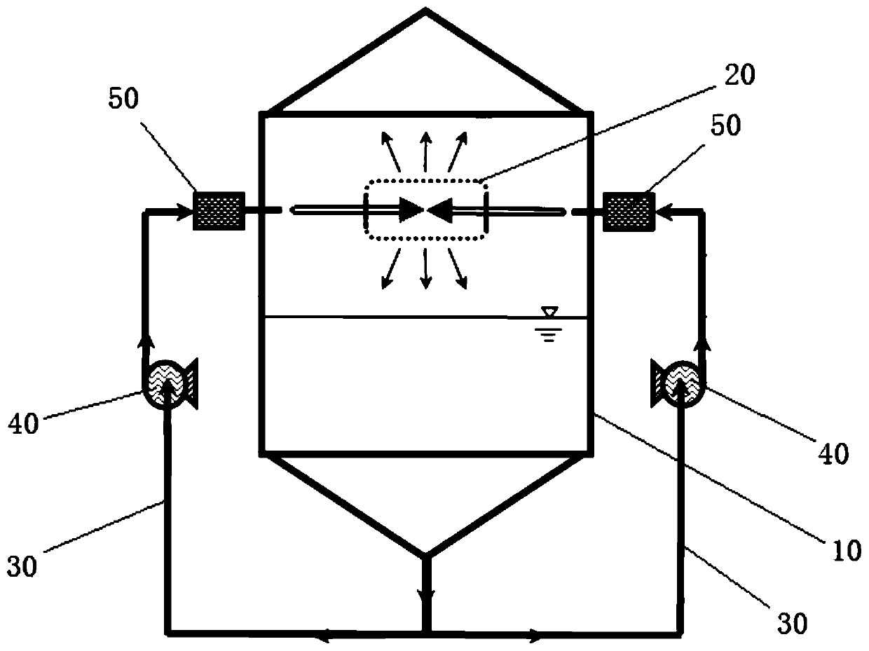
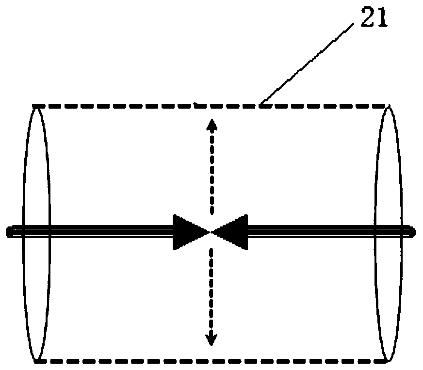
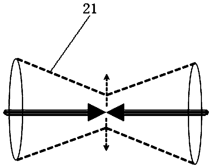
[0090] use figure 1 The reaction device shown, in which the non-submerged impinging flow reaction module adopts figure 2 Shown, carry out the catalytic hydrogenation of vacuum residuum to prepare light chemical oil (gasoline and diesel oil), process condition is as follows:

[0091] The liquid mixed raw materials of vacuum residue, hydrogen and catalyst are sprayed into the inlets on both sides of the non-submerged impinging flow reaction module through the nozzle. After the impact, the secondary fluid diffuses at 90° with the direction of movement of the raw material, and has a secondary impact with the cylinder and the multiple pore structures set on it, and cavitation and shear effects destroy the molecular bonds. The qualitative product is collected from above the reaction housing. After strengthening, the unreacted material or the heavy part after the reaction falls into the bottom of the reaction shell in liquid phase, and returns here to react through the driving dev...


PUM

PropertyMeasurementUnit
pore sizeaaaaaaaaaa

Abstract

The invention provides a liquid non-submerged impinging stream reaction device and reaction method. The device comprises a reaction shell and a non-submerged impinging stream reaction component, the reaction shell has a cavity, and the non-submerged impinging stream reaction component is arranged in the cavity for completing a reaction of a jet fluid of a liquid raw material under the action of non-submerged impinging, cavitation and shearing. The device and method provided by the invention utilize the non-submerged impinging stream reaction component to complete the chemical reaction of the liquid raw material in the non-submerged impinging, cavitation and shearing process, so that the reinforcing effect on the liquid raw material fluid can be significantly improved, and the fluid can react efficiently under milder reaction conditions.

Description

technical field [0001] The invention relates to the field of organic chemistry, in particular to a liquid non-submerged impinging flow reaction device and a reaction method. Background technique [0002] Two continuously moving liquids or two continuously moving gases (both known as continuous phase working fluids) collide with each other in opposite motion, which is defined as impinging flow. Experiments have proved that installing a solid partition on the impact point of two continuous-phase impinging flows does not change the nature of the impinging flow. Therefore, when a single continuous-phase working fluid (gas or liquid) hits a solid partition or different solid components, the same It has all the characteristics of impinging flow, so it can also be defined as impinging flow. The liquid in the continuous phase can also be mixed with a small amount of gas, solid or gas plus solid (called sparse phase); the gas in the continuous phase can also be mixed with a small am...

Claims


Application Information

Patent Timeline
Patent Type & Authority Applications(China)
IPC IPC(8): B01J19/26C10G47/24
CPCB01J19/0053B01J19/26C10G47/24C10G2300/1077
Inventor 张其凯徐鹏辉
Owner 捷创(东营)能源技术有限责任公司
Why Eureka
Try Eureka