Electric turning system of ship propeller, ship propeller and ship and boat
A technology of electric steering system and thruster, which is applied in ship propulsion, rudder steering, propulsion components, etc. It can solve the problems of inconvenient installation and maintenance, complicated operation, complex structure, etc., and achieve compact structure, flexible installation position and simple installation quick effect
Active Publication Date: 2019-08-23
DONGGUAN EPROPULSION INTELLIGENCE TECH LTD
11 Cites 2 Cited by
AI-Extracted Technical Summary
Problems solved by technology
[0007] The technical problem to be solved by the present invention is to provi...
Method used
(3) The whole electric steering drive device is built-in and fixed in the steering connection pipe of the marine propeller through the screw mandrel and the joint, without the need to increase the mechanism in parallel with the steering connection pipe outside as in the prior art, and the external increase mechanism should be considered The volume of the entire driving device is likely to cause interference, especially the use of hydraulic driving devices, which is generally large in size and affects compatibility. The electric steering drive can be adapted to different propellers with the advantage of its small size.
As shown in Figure 9, described position switch 310 is reed switch, and described position switch 310 detects by sensing described magnet 311 and is used for detecting described first position and/or second position, with Realize position calibration and limit protection.
Because the motor driver 320 and the first controller 330 are all integrated in the housing of the motor 301, the motor 301 is sealed using a dynamic seal 309, which can play a waterproof role to protect the motor 301 and other electronic components in the housing .
In other embodiments, the output shaft 3013 of the motor 301 is a hollow shaft, the screw mandrel 302 extends axially through the output shaft 3013 of the motor 301, and the left and right ends of the motor 301 are formed by support bearings and double row angular contact bearings. The screw rod 302 is supported to increase the coaxiality of the motor 301 and the screw screw 302. At the same time, the double-row angular contact bearing is used to bear the axial force, and the motor 301 does not need to bear the axial force.
Steering base 401 is connected by upper housing base 4011, lower housing base 4012 to form a closed shell structure, between upper housing base 4011, lower housing base 4012, sealing groove and sealing ring 412 are arranged, and are compressed and sealed by threads Ring 412 is sealed and waterproof. The place where the upper shell seat 4011 is connected with the steering shaft 403 is provided with a dynamic sealing structure, which also plays a waterproof role.
The marine propeller electric steering system provided by the embodiment of the present invention, the marine propeller and the boat, the electric steering drive unit 30 and the steering gear 40 have no direct mechanical connection, so the installation position of the steering gear can be very flexible, and the whole marine The propeller electric steering system is small in size, com...
Abstract
The invention belongs to the technical field of turning of ships and boats, and particularly relates to an electric turning system of a ship propeller, the ship propeller and a ship and a boat. The electric turning system of the ship propeller comprises an electric turning driving device and conning device, wherein the electric turning driving device is fixedly connected to a fixing assembly of the ship propeller; the electric turning driving device is rotatably connected to the first end of a connecting rod, and the second end of the connecting rod is rotatably connected to a rotating assembly; the conning device is used for sending a turning signal to the electric turning driving device based on the user operation; the electric turning driving device comprises a motor which rotates to drive the connecting rod to rotate; and the connecting rod in rotating drives the rotating assembly of the ship propeller to vertically axially rotate so as to adjust the propelling direction of the ship propeller. According to the electric turning system of the ship propeller, the electric turning driving device is not directly mechanically connected to the conning device; the mounting position ofthe conning device is flexible; and the whole electric turning system of the ship propeller is small in size, compact in structure, and simple and quick to mount.
Application Domain
Steering ruddersOutboard propulsion units +1
Technology Topic
PropellerElectric machinery +2
Image
Examples
- Experimental program(1)
Example Embodiment
[0040] In order to make the technical problems, technical solutions and beneficial effects solved by the present invention clearer, the following further describes the present invention in detail with reference to the accompanying drawings and embodiments. It should be understood that the specific embodiments described herein are only used to explain the present invention, but not to limit the present invention.
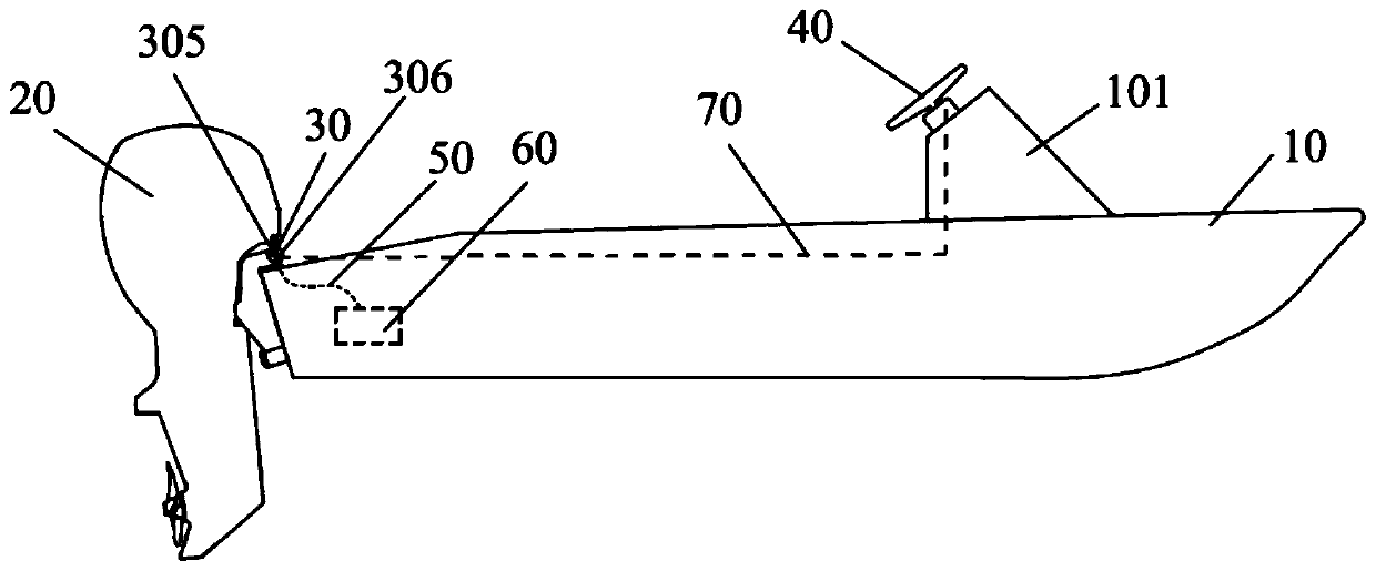
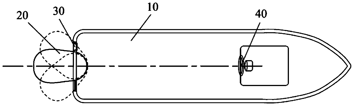
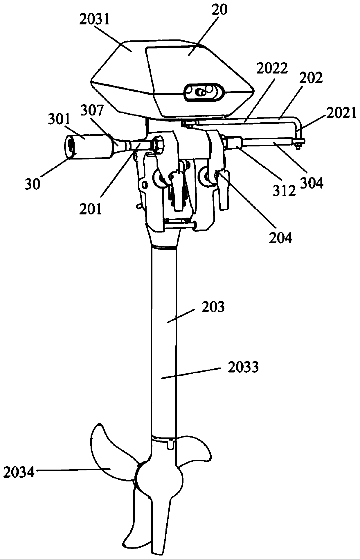
[0041] Such as Figure 1 to Figure 5 As shown, an embodiment of the present invention provides a boat, including a hull 10, a marine propeller 20, and a marine propeller electric power steering system. The marine propeller 20 includes a fixed assembly, a connecting rod 202, and a rotating assembly 203. The fixed assembly and The hull 10 is fixedly connected, and the rotating component 203 is connected to the fixed component and can rotate relative to the fixed component along a vertical axis.
[0042] The marine propeller electric steering system includes an electric steering drive device 30 and a steering device 40; the fixed assembly has a steering connection pipe 201 arranged in a horizontal direction, and the electric steering drive device 30 is fixedly connected to the steering connection pipe 201 The electric steering drive device 30 and the rotating assembly 203 are connected by the connecting rod 202.
[0043] The steering device 40 is used to send a steering signal to the electric steering drive device 30 based on a user's operation. The electric steering drive device 30 includes a motor 301, which drives the connecting rod 202 to rotate. The rod 202 drives the rotating assembly 203 of the marine propeller to rotate in a vertical axial direction so as to adjust the propulsion direction of the marine propeller 20.
[0044] The steering signal includes a direction (counterclockwise or clockwise) and an angle signal (angle size), where the angle signal is measured by a position sensor, and the direction is calculated and determined by the second controller based on multiple angle signals.
[0045] Here, the first controller is the controller of the electric steering drive device 30, and the second controller is the controller of the steering device 40.
[0046] The electric steering drive device 30 drives the first end of the connecting rod 202 to move in a direction parallel to the axial direction of the steering connecting pipe 201, and the first end of the connecting rod 202 has a first end closest to the motor 301. A position and a second position farthest from the motor 301, when the steering device 40 is at the minimum rotation angle position and the maximum rotation angle position, respectively correspond to the first position and the second position.
[0047] The first end of the connecting rod 202 has a third position between the first position and the second position. In the third position, the distance between the vertical midplane of the marine propeller and the steering connecting pipe is The included angle is 90°. At this time, the vertical midplane of the marine propeller 20 is parallel to the long axis direction of the boat, and the propulsion direction of the marine propeller 20 is straight forward. Such as image 3 As shown, the fixed assembly further includes a clamp 204, and the rotating assembly 203 includes a propeller housing and a propeller 2034. A power unit 2035 is installed in the propeller housing. The power device 2035 is connected to the propeller 2034 and drives the propeller 2034 to rotate; the first end of the connecting rod 202 is connected to the propeller housing, and the electric steering drive device 30 drives the connecting rod 202 When rotating, the connecting rod 202 drives the rotating assembly 203 to rotate to adjust the orientation of the propeller 2034 in the horizontal direction, thereby adjusting the propulsion direction of the marine propeller.
[0048] The power unit 2035 can be installed on the upper and lower parts of the propeller housing. When installed on the upper part of the propeller housing, a vertical transmission shaft (the propeller main shaft 2032 described below) is set between the power unit 2035 and the propeller 2034 and then connected to the propeller 2034; when installed in the lower part of the propeller housing, the power unit 2035 is coaxially connected with the propeller 2034.
[0049] In one embodiment, such as Figure 5 As shown, the power unit 2035 is installed on the upper part of the propeller housing. The propeller housing includes an upper shell 2031 and a spindle support shell 2033. The upper shell 2031 is fixed above the spindle support shell 2033. The power unit 2035 is installed in the upper casing 2031, the propeller 2034 is installed on the rear side of the lower end of the main shaft support casing 2033, and the upper end of the propeller main shaft 2032 is connected to the output shaft of the power unit 2035 through a gear box assembly , The lower end of the propeller main shaft 2032 is connected to the propeller 2034 through two orthogonally meshed bevel gears, and a vertical propeller main shaft 2032 is arranged between the power device 2035 and the propeller 2034, that is, the power device 2035 and The propeller 2034 is connected by the propeller main shaft 2032. In this way, the rotation of the power device 2035 can drive the propeller 2034 to rotate so as to provide propulsion power for the boat. The marine propeller 20 is suspended from the stern of the hull 10 by a clamp 204, the steering connecting pipe 201 is arranged on the clamp 204 in a horizontal direction, and the marine propeller electric power steering system is fixed in the steering connecting pipe 201. The electric steering drive device 30 is fixedly connected to the steering connecting pipe 201. One end of the connecting rod 202 is hinged to the upper part of the pusher 203 (for example, hinged by bolts and nuts). Preferably, one end of the connecting rod 202 is hinged on the bottom surface of the upper shell 2031.
[0050] The power device 2035 may be a motor.
[0051] Such as Figure 3 to Figure 13 As shown, the electric steering drive device 30 further includes a first controller 330, a motor driver 320, a screw rod 302, a screw nut 303, and a motor rotation detection element 350; one end of the screw rod 302 and the motor The output shaft of 301 is fixedly connected, and the lead screw 302 is parallel to the steering connecting pipe 201.
[0052] The lead screw 302 is parallel to the steering connecting pipe 201 in two situations. The first is that the lead screw 302 is arranged outside the steering connecting pipe 201 and spaced parallel to the steering connecting pipe 201; The second type is that the lead screw 302 is arranged inside the steering connecting pipe 201 and coaxial with the steering connecting pipe 201. In order to reduce the volume of the electric power steering system of the marine propeller, it is preferable that the lead screw 302 is provided inside the steering connecting pipe 201.
[0053] The screw nut 303 is threadedly connected to the outside of the screw rod 302, and the screw nut 303 is connected to the first end of the connecting rod 202. Here, the lead screw nut 303 and the first end of the connecting rod 202 may be directly connected, or may be connected through a push rod 304 described below.
[0054] The first controller 330 is configured to send a control signal to the motor driver 320 according to the steering signal to control the rotation direction and the number of turns of the motor 301, and the motor driver 320 is configured to receive the control signal to drive the The motor 301 runs; the rotation of the motor 301 drives the screw rod 302 to rotate so that the screw nut 303 moves linearly along the screw rod 302 and drives the connecting rod 202 to move.
[0055] The motor rotation number detection element 350 is used to detect the number of rotations of the motor 301 and feed it back to the first controller 330. The first controller 330 controls the operation of the motor 301 accordingly, so that The first end of the connecting rod 202 is located in the range between the first position and the second position. Based on the number of rotations of the motor 301 detected by the motor rotation number detection element 350, the first controller 330 can control the motor 301 in a closed loop accordingly. In this way, the feedback adjustment of the motor 301 can be realized.
[0056] The motor rotation number detection element 350 may be a Hall sensor or an encoder. In an embodiment, the electric steering drive device 30 further includes a push rod 304, the screw nut 303 is connected to the first end of the connecting rod 202 through the push rod 304, and the push rod 304 is hollow. Push rod, the screw 302 and the screw nut 303 are arranged in the steering connecting pipe 201 and are coaxially arranged with the steering connecting pipe 201, and the screw nut 303 drives the push rod 304 along The lead screw 302 moves linearly to drive the first end of the connecting rod 202 to move linearly along the lead screw 302, and both the first position and the second position are located on the lead screw 302.
[0057] The electric steering drive device 30 also includes a position switch 310 for detecting the first position and/or the second position. The position switch 310 is electrically connected to the first controller 330 and sends a switch signal to the The first controller 330, after receiving the switch signal, controls the motor 301 to stop or reversely rotate.
[0058] The position switch 310 can also be replaced by a position sensor, such as a photoelectric sensor or an ultrasonic sensor, for sending the detected distance information to the first controller 330, and the first controller 330 controls the distance according to the distance information. The operation of the motor 301.
[0059] The electric steering drive device 30 also includes a position switch for detecting the third position. The third position is located on the lead screw 302. The position switch for detecting the third position may be an angle sensor for detecting the rotation angle of the marine propeller, or a photoelectric sensor or an ultrasonic sensor for detecting the center position of the marine propeller.
[0060] The stroke range of the push rod 304 is the same as the stroke range of the lead screw nut 303. The position of the lead screw nut 303 on the lead screw 302 corresponds to the rotation stroke of the steering device 40, and the angular position of the steering device 40 corresponds to the lead screw. The only position of the nut 303 on the lead screw 302.
[0061] The motor driver 320 is installed at one end of the motor 301 away from the steering connecting pipe 201. Preferably, the first controller 330 and the motor driver 320 are integrated in the housing of the motor 301.
[0062] The housing of the motor 301 includes a front housing 3011 and a rear housing 3012. The stator assembly and the rotor assembly of the motor 301 are arranged in the front housing 3011. The front housing 3011 includes a cylindrical portion 30111 and is located in the stator The radial extension part 30112 behind the assembly and the rotor assembly, the rear housing 3012 is fixed to the rear end of the front housing 3011 (the cylindrical part 30111), the cylindrical part 30111, the radial extension part 30112 and the rear housing 3012 A cavity is formed in between, and the motor driver 320 is installed behind the radial extension 3012 and accommodated in the cavity. The rear housing 3012 is provided with a power cord connector 305 and a signal cord connector 306, and the motor driver 320 is electrically connected to a power source through the power cord connector 305 to supply the motor 301, the first controller 330 and the motor coil through the power source. The number detection element 350 is powered, and the first controller 330 is electrically connected to the steering device 40 through the signal line connector 306.
[0063] In an embodiment, the front part of the motor 301 forms a cavity where the motor driver 320 and the first controller 330 are installed. At this time, the power cord connector 305 and the signal cord connector 306 are preferentially arranged on the front housing 3011 of the motor 301.
[0064] The rear shell 3012 and the front shell 3011 are hermetically connected by static seals, and the front shell 3011 is connected to the following joint 307 (such as image 3 A sealed connection is also provided between the connector 307 and the screw rod 302, and a sealed waterproof chamber is formed between the rear housing 3012, the front housing 3011, and the connector 307, so that the motor 301, the first controller 330, the motor driver 320 and the position switch 310 are arranged in a sealed and waterproof environment for protection.
[0065] Such as figure 1 and figure 2 As shown, the power cord connector 305 is electrically connected to the power source 60 through the power cord 50. The signal line connector 306 communicates with the steering device 40 through a signal line 70, and the first controller 330 communicates with the steering device 40 by wire.
[0066] In one embodiment, such as Figure 13 As shown, the electric steering drive device 30 is connected to the power supply 60 of the marine propeller 20 through a power cord 50 to supply power to the first controller 330 and the motor driver 320. The steering device 40 has its own power supply 440 to supply power, and the steering device 40 and the electric steering drive device 30 Wireless communication.
[0067] In another embodiment, the steering device 40 is wiredly connected to the electric steering drive device 30, the steering device 40 is in wired communication with the electric steering drive device 30, and the steering device 40 is powered by the electric steering drive device 30, and the steering device 40 is connected to the electric steering drive device 30. The device 30 shares a power source, and the marine propeller 20 uses a power source 60. Alternatively, the steering device 40 and the electric steering drive device 30 share the power source 60 with the marine propeller 20.
[0068] The electric steering drive device 30 further includes a joint 307 for connecting the motor 301 and the steering connecting pipe 201, one end of the joint 307 is fixedly connected to the housing of the motor 301 by screws, and the joint 307 The other end of the steering connection pipe 201 is threadedly connected to the outside of one end of the steering connection pipe 201. Specifically, the end of the joint 307 with a smaller outer diameter is provided with an internal thread, and one end of the steering connecting pipe 201 is provided with an outer thread that matches the inner thread provided at the end of the joint 307 with a smaller outer diameter.
[0069] The joint 307 and the steering connecting pipe 201 are connected by threads, and no installation tools are required, which greatly simplifies the installation steps and is plug and play.
[0070] The screw rod 302 passes through the joint 307 and is connected to the motor 301. The inner hole of the joint 307 is provided with a double row angular contact bearing 308 and a dynamic seal 309. The outer side of the double row angular contact bearing 308 The inner ring of the joint 307 is interference fit, the inner ring of the double-row angular contact bearing 308 is sleeved on the screw rod 302, the outer ring of the dynamic seal 309 and the inner wall of the joint 307 Hole wall interference assembly, the inner ring of the dynamic seal 309 is sleeved on the screw rod 302, the double row angular contact bearing 308 is located behind the dynamic seal 309, and the dynamic seal 309 is used for The motor 301 is sealed.
[0071] Since the motor driver 320 and the first controller 330 are integrated in the housing of the motor 301, the motor 301 is sealed by the movable seal 309, which can play a waterproof role to protect the motor 301 and other electronic components in the housing.
[0072] In other embodiments, the joint 307 and the steering connecting pipe can also be fixed with a shaft, and the double row angular contact bearing can also be replaced with two angular contact bearings or other bearings or bearing combinations that can withstand bidirectional axial force.
[0073] The position switch 310 is arranged in the connector 307 and is electrically connected to the first controller 330.
[0074] One end of the push rod 304 is slidably inserted into the steering connecting pipe 201 and is sleeved and connected to the other end of the screw rod 302, and the screw nut 303 is fixed on the push rod 304 near the motor 301 on the inner wall of the end. The electric steering drive device 30 further includes a magnet 311 fixed at the end of the push rod 304 close to the motor 301 or the end of the screw nut 303 close to the motor 301, so The magnet 311 follows the push rod 304 to move.
[0075] The magnet 311 may be fixed on the push rod 304 close to the end of the motor 301, or fixed on the screw nut 303 close to the end of the motor 301, depending on which position is closest to the position switch 310.
[0076] Such as Picture 9 As shown, the position switch 310 is a reed switch, and the position switch 310 detects the first position and/or the second position by sensing the magnet 311, so as to realize position calibration and limit position protection.
[0077] Because the distance between the magnet 311 and the position switch 310 is required, the position switch 310 must be installed at the starting position (front end) of the push rod 304 for detection. The signal line of the position switch 310 needs to be connected to the first controller 330, and the position switch 310 sends a switch signal to the first controller 330, and the first controller controls the motor 301 to stop or reversely run after receiving the switch signal.
[0078] The distance between the magnet 311 and the position switch 310 is close to a certain threshold, the state of the position switch 310 changes, the controller controls the motor 301 to stop running, and records the motor rotation number detection element 350 (encoder or hall sensor) after the motor 301 stops rotating The number of turns the motor 301 rotates, this value is used as a reference value, and the current push rod 304 (connecting rod 202) position is calculated according to the direction and number of turns of the motor 301 next.
[0079] After the electric power steering system is powered on, the push rod 304 moves toward the motor 301. When the position switch built in the connector 307 detects that the magnet strength of the magnet 311 installed on the push rod 304 reaches a certain threshold by non-contact detection, the control The current position recorded by the device is the initial position. A Hall sensor or encoder is installed in the motor driver 320 to detect the rotation direction and number of turns of the motor. The theoretical maximum number of rotations of the motor 301 is stored in the first controller 330. According to the stroke length L of the screw rod 302, assuming that the feed of the screw rod 302 to the push rod for each revolution of the motor 301 is l, the motor 301 will start from The theoretical maximum number of rotations that can be rotated from the zero point is Δn=L/l. The first controller 330 obtains the number of forward and reverse rotations of the motor 301 through the position sensor, and limits the actual number of rotations relative to the initial position of the rotation. The number increment does not exceed Δn.
[0080] In other embodiments, the position switch 310 may also be a Hall switch, a photoelectric switch or a Hall sensor, a photoelectric sensor, or an ultrasonic sensor.
[0081] The electric steering drive device 30 further includes a supporting sliding sleeve 312, one end of the supporting sliding sleeve 312 is threadedly connected to the steering connecting pipe 201, and the push rod 304 is in sliding contact with the inner wall of the supporting sliding sleeve 312.
[0082] The outer wall of the screw rod 302 is guided by the inner wall of the push rod 304, and the outer wall of the push rod 304 contacts the support sliding sleeve 312 to form an outer guide. The support sliding sleeve 31 provided on the push rod 304 can support the free end of the push rod 304 to reduce radial runout.
[0083] In one embodiment, the screw rod 302 and the output shaft of the motor 301 are integrally formed.
[0084] In other embodiments, the output shaft 3013 of the motor 301 is a hollow shaft, and the screw rod 302 extends through the output shaft 3013 of the motor 301 in the axial direction. The left and right ends of the motor 301 are opposed to the screw rod by support bearings and double row angular contact bearings. 302 is supported to increase the coaxiality of the motor 301 and the lead screw 302. At the same time, the double row angular contact bearing is used to bear the axial force, and the motor 301 does not need to bear the axial force.
[0085] In an embodiment of the marine propeller 20, the connecting rod 202 is L-shaped. The connecting rod 202 includes a vertical rod section 2021 and a horizontal rod section 2022. One end of the horizontal rod section 2022 is connected to the vertical rod section 2022. The upper end of the straight rod section 2021, the other end of the horizontal rod section 2022 is hinged to the rotating assembly 203, and the electric steering drive device 30 is rotatably connected with the lower end of the vertical rod section 2021.
[0086] In a specific embodiment, the other end of the horizontal rod section is hinged to the upper part of the propeller housing, and the lead screw nut 303 is connected to the lower end of the vertical rod section 2021 through the push rod 304. The other end of the push rod 304 is provided with a through hole, the lower end of the vertical rod section 2021 is provided with an external thread, and the lower end of the vertical rod section 2021 penetrates the through hole downward and is screwed with a nut. In this way, the connecting rod 202 and the push rod 304 are hinged. Specifically, the horizontal rod section 2022 is hinged on the bottom surface of the upper shell 2031 of the propeller housing. The rotation axis of the horizontal rod section 2022 is spaced parallel to the central axis of the thruster main shaft 2032. To ensure the flexible rotation of the connecting rod 202.
[0087] In other embodiments, the first end of the connecting rod connected with the motor drive device and the second end of the connecting rod connected with the rotating assembly have the same height in the vertical direction, and the connecting rod may also be straight. Rod; In other embodiments, the connecting rod can also be a rod with at least one horizontal rod section in other shapes.
[0088] When the push rod 304 moves back and forth along the screw rod 302, through the principle of connecting rod crank, the push rod 304 can drive the connecting rod 202 to move, and the connecting rod 202 is hinged with the propeller 203, which can directly or indirectly push the rotating assembly 203 in the vertical direction The axis of rotation. On the same marine propeller 20, the stroke range of the push rod 304 and the rotation stroke of the steering device 40 are mapped one by one. The mapping relationship can be linear or non-linear, but the angle signal input by the steering device 40 can be combined with The positions of the push rods 304 are in one-to-one correspondence, thereby achieving the purpose of adjusting the steering. The L-shaped connecting rod 202 can drive the upper shell 2031 of the rotating assembly 203 to rotate together with the main shaft support shell 2033 and the propeller 2034, thereby changing the orientation of the marine propeller 20.
[0089] Such as Figure 7 As shown, the output shaft 3013 of the motor 301 is coaxially arranged with the screw rod 302, and the output shaft 3013 of the motor 301 and the screw rod 302 are separately arranged.
[0090] In other embodiments, the motor 301 and the screw rod 302 may be connected in different axes. Different shaft connection mainly considers that the installation position of part of the ship's propeller of the stern plate will sink and sink. Through different shaft connection, the overall length of the electric steering drive device 30 after installation can be reduced to adapt to this type of installation.
[0091] Preferably, the output shaft 3013 of the motor 301 is a hollow shaft, one end of the screw rod 302 is inserted into the output shaft 3013 of the motor 301, the screw rod 302 is provided with a pin hole, and one end of the screw rod 302 The output shaft 3013 of the motor 301 is fixedly connected with a rotating pin 313 inserted into the pin hole.
[0092] In other embodiments, one end of the screw rod 302 and the output shaft 3013 of the motor 301 may also be connected by a coupling.
[0093] In other embodiments, the output shaft 3013 of the motor 301 is integrated with the screw rod 302, so that the number of connecting parts can be reduced.
[0094] The electric steering drive device 30 also includes a current sensor for measuring the current value of the motor 301 or the motor driver 320, the current sensor is electrically connected to the first controller 330, and the first controller 330 is When the current value exceeds a set threshold, the motor 301 or the motor driver 320 is controlled to stop running.
[0095] The current sensor may be a Hall current sensor or a current detection circuit for detecting the working current of the motor 301. If the operating current of the motor 301 exceeds a certain range of its rated operating current, it may be that the motor is abnormal or the motor is blocked, so as to control the motor 301 to stop running to protect the electric steering drive device 30.
[0096] The electric steering drive device 30 also includes a temperature sensor that measures the temperature of the motor 301 or the motor driver 320, the temperature sensor is electrically connected to the first controller 330, and the first controller 330 The temperature value exceeds the set threshold to control the motor 301 or the motor driver 320 to stop running.
[0097] Such as figure 1 , Figure 10 to Figure 12 As shown, the steering device 400 includes a steering wheel 402, a steering shaft 403, a planetary reducer, and an angle detection mechanism; the input end of the planetary reducer is connected to the steering shaft 403, and the angle detection mechanism is used to detect the The rotation angle of the output end of the planetary reducer.
[0098] The steering device 40 also includes a steering base 401 and a rotary damper 404. The steering base 401 has an inner cavity, the rotary damper 404 and the angle detection mechanism are arranged in the inner cavity, and the steering base 401 is installed in the inner cavity. On the console 101 on the hull 10, the steering wheel 402 is fixed on the upper end of the steering shaft 403, and the lower end of the steering shaft 403 is rotatably inserted into the steering base 401 and extends into the inner cavity The inner ring of the rotary damper 404 is fixed to the steering shaft 403, and the outer ring of the rotary damper 404 is fixed to the steering base 401, so as to generate damping during rotation.
[0099] The planetary reducer includes a sun gear shaft 405, a planet gear 406, a planet carrier 407, and a ring gear 408. A sun gear 4051 is formed on the sun gear shaft 405, and the upper end of the sun gear shaft 405 is fixedly connected to the lower end of the steering shaft 403. The planetary gear 406 is meshed between the sun gear 4051 and the ring gear 408, the outer part of the ring gear 408 is fixed in the steering base 401, and the planet gear 406 is rotatably supported by a pin 409 On the planet carrier 407, the planet carrier 407 is located below the ring gear and is rotatably supported at the lower end of the sun gear shaft 405 through a bearing.
[0100] The angle detection mechanism includes a magnetic element 410 and a Hall position sensor 411. The magnetic element 410 is fixed on the planet carrier 407, and the Hall position sensor 411 is fixed at the bottom of the cavity. The position sensor 411 senses the change in the position of the magnetic element 410 to detect the rotation angle of the planet carrier 407.
[0101] The magnetic element 410 is a Hall magnet or a magnetic element.
[0102] In addition, the angle detection mechanism may be provided with multiple Hall position sensors 411 to increase detection accuracy and reliability, and the angle detection mechanism may also use other position sensors other than the Hall position sensor 411, such as photoelectric position sensors.
[0103] When only one Hall position sensor 411 is used, the Hall position sensor 411 must be installed below the axis of the steering shaft 403, and the magnetic element 410 can be installed directly opposite to the Hall position sensor 411, or it can be installed The place facing the Hall position sensor 411 is preferably installed below the Hall position sensor 411.
[0104] When multiple (more than two) Hall position sensors 411 are used, the multiple Hall position sensors 411 are generally distributed on a circumference coaxial with the steering shaft 403, and the magnetic element 410 is located on the axis of the steering shaft 403.
[0105] Because the lower end of the steering shaft 403 is connected to a planetary reducer, on the one hand, it is used to reduce the rotation angle of the steering shaft 403, because the rotatable rotation stroke N designed for the steering wheel 402 is greater than 360°, which exceeds the Hall position sensor 411 The Hall position sensor 411 can only detect a rotation stroke of less than 360°, so a planetary reducer is installed at the lower end of the steering wheel 402. Assuming that the reduction ratio of the planetary reducer is Z, the rotation stroke that needs to be detected can be converted into Check the rotation stroke N/Z. On the other hand, in combination with the rotary damper 404, when the steering wheel 402 rotates to any angle, the user releases both hands to keep the steering wheel 402 in the original position. The user does not need to hold the steering wheel 402 continuously, and the steering wheel 402 can stay in any free state. position.
[0106] For example, the rotation stroke of the steering wheel 402 is usually 3 turns (that is, 1080°), and the Hall position sensor 411 can only detect the angle change of one turn, so the maximum rotation of the steering wheel 402 can be determined by a 4:1 planetary reducer. The angle is converted to 270° to meet the angle detection range of the Hall position sensor 411.
[0107] A rotating damper 404 is provided on the steering shaft 403 to increase the rotation damping of the steering wheel 402 to prevent excessive rotation due to too small damping.
[0108] The steering shaft 403 and the steering wheel 402 are connected to the steering base 401 below, and the standard connection method of the steering wheel can be used. The steering base 401 is provided with a connection interface. The user can replace the steering shaft 403 and the steering wheel 402 with the desired installation size according to the size of the boat.
[0109] The steering base 401 is connected by an upper shell seat 4011 and a lower shell seat 4012 to form a closed shell structure. A sealing groove and a sealing ring 412 are provided between the upper shell seat 4011 and the lower shell seat 4012, and the sealing ring 412 is pressed by the thread. Sealed and waterproof. A dynamic sealing structure is provided where the upper shell base 4011 and the steering shaft 403 are connected, which also plays a waterproof role.
[0110] The steering device 40 also includes a second controller 420, which is respectively communicatively connected with the first controller 330 and the Hall position sensor 411, and the second controller 420 is used to connect the Hall The rotation angle of the planet carrier 407 (magnetic element 410) collected by the position sensor 411 is converted into a steering signal and sent to the first controller 330, so that the steering device 40 is at the minimum rotation angle position and the maximum rotation angle position. The first position and the second position of the connecting rod 202 correspond to each other.
[0111] In some embodiments, such as Figure 13 As shown, the first controller 330 is provided with a first wireless communication module 340, and the second controller 420 is provided with a second wireless communication module 430. The first wireless communication module 340 communicates with the second wireless communication module 430. The communication between the communication modules 430 realizes the wireless communication between the electric steering drive device 30 and the steering device 40.
[0112] In other embodiments, the electric steering drive device 30 and the steering device 40 are connected by a cable, and the electric steering drive device 30 and the steering device 40 are in wired communication.
[0113] Such as Figure 13 As shown, the steering device 40 has its own power supply 440.
[0114] The steering device 40 also includes an indicator light, a power switch 450 and a communication interface. The indicator light, the power switch 450 and the communication interface are respectively electrically connected to the second controller 420. The indicator light, the power switch 450 and the communication interface are exposed. The outer surface of the steering base 401. The indicator light is used to indicate at least one of the left deflection state of the marine propeller, the power-on state of the steering device 40, and whether the power supply is sufficient.
[0115] The second controller 420 controls the status of the indicator light to display the current working mode or position of the steering wheel 402, for example, to display whether the steering wheel 402 is currently rotating counterclockwise or clockwise, or to display the current steering direction of the boat Counterclockwise or clockwise can also be used to indicate the status of the power supply 440 built in the steering device 40, such as normal power or low power. It can also be used to prompt the second controller 420 or communication failure.
[0116] The steering device 40 also includes a port and port switch for selectively installing the electric steering drive device 30 in a port or starboard position.
[0117] In an embodiment, the steering device 40 further includes a display screen for displaying the left deflection state of the marine propeller (whether the propeller is oriented to the left or right), the left deflection angle of the marine propeller, and the steering device is powered on. At least one of the status (whether power is on) and the power information of the power supply (remaining power, whether the power is sufficient). The display screen can replace the above-mentioned indicator lights.
[0118] The steering device 40 also includes a zero position input key for correcting the zero position of the steering device 40. In the process of setting up the electric steering system, turn the steering device 40 so that the electric steering drive device 30 adjusts the direction of the propeller to a position where the propulsion direction of the boat is straight ahead. Press the zero input key at this position to make the steering device 40 The second controller saves the position information of the steering device 40 at this time, and records this position as the zero position of the steering device 40.
[0119] When the steering device 40 is in the zero position, the indicator light on the steering device 40 will show that the steering device 40 is in the zero position at this time. When the steering device 40 is not at the zero position, the indicator light of the steering device 40 will display whether the steering device 40 is in the left or right position, so that the user can understand whether the propeller is currently in the left or right direction.
[0120] The power switch 450 controls the power-on and power-off of the steering device 40, and only the power-on state can work. The communication interface can perform wired communication with the electric steering drive device 30.
[0121] The working principle of the steering device of this embodiment is as follows:
[0122] The user rotates the steering wheel 402 to drive the steering shaft 403 and the planetary reducer to rotate together. The position sensor 410 sends the angle signal (analog) of the planetary reducer detected to the second controller 420, and the second controller 420 responds to the signal Perform analog-to-digital conversion and convert it into a digital signal (turn signal), and then send the turn signal to the first controller 330 of the electric steering drive device 30 through a wireless communication module or wired transmission, and the electric steering drive device 30 will respond to the turn signal The rotation of the driving motor 301 adjusts the propulsion direction of the marine propeller 20.
[0123] The electric steering drive device 30 is powered by the power source of the marine propeller 20 or an external power source. The steering device 40 may be powered by a built-in power source, or may be powered from the electric steering drive device 30 through a cable.
[0124] When the marine propeller 20 is an electric marine propeller, the power source 60 of the marine propeller 20 is generally used for power supply.
[0125] In other alternatives, the steering device 40 with the above structure can be replaced by a button handle, which is similar to a game handle, that is, the buttons on the handle can be used to control clockwise/counterclockwise steering and increase and decrease the steering angle.
[0126] In the marine propeller electric steering system, marine propeller and boat provided by the embodiment of the present invention, the electric steering drive device 30 and the steering device 40 are not directly mechanically connected, so the installation position of the steering device can be very flexible. The steering system is small in size, compact in structure, simple and quick to install, and can be well compatible with different types of marine propellers, and is also better compatible with electric marine propellers.
[0127] In addition, the marine propeller electric steering system also has the following advantages:
[0128] (1) It supports wired and wireless installation, avoiding complicated installation steps, and at the same time, there is no complicated oil circuit, and there is no risk of oil leakage. It can run for a long time in high and low temperature environments and is maintenance-free.
[0129] (2) The motor drive provides steering torque, which greatly reduces the burden on the operator and makes steering easier.
[0130] (3) The entire electric steering drive device is fixed in the steering connecting pipe of the marine propeller through the screw rod and the joint. There is no need to add a mechanism parallel to the steering connecting pipe on the outside as in the prior art, and the entire drive device should be considered when adding a mechanism outside. The size of the device is likely to cause interference, especially when using hydraulic drive devices, which are generally large in size, which affects compatibility. The electric steering drive device can adapt to different thrusters with the advantage of small size.
[0131] The above are only the preferred embodiments of the present invention and are not intended to limit the present invention. Any modification, equivalent replacement and improvement made within the spirit and principle of the present invention shall be included in the protection of the present invention. Within range.
PUM


Description & Claims & Application Information
We can also present the details of the Description, Claims and Application information to help users get a comprehensive understanding of the technical details of the patent, such as background art, summary of invention, brief description of drawings, description of embodiments, and other original content. On the other hand, users can also determine the specific scope of protection of the technology through the list of claims; as well as understand the changes in the life cycle of the technology with the presentation of the patent timeline. Login to view more.
Similar technology patents
Vertical belt middle sampling head
ActiveCN101551305AFlexible installation positionThe sampling section is complete
Owner:浙江杭钻机械制造股份有限公司
Vein-fingerprint-face composite recognition system with automatic light brightness control function
Owner:成都折衍科技有限公司
System and method for online detecting life of CMP polishing pad
InactiveCN109454547AFlexible installation positionMinor changes
Owner:HANGZHOU ZHONGGUI ELECTRONICS TECH CO LTD
Truck overload monitoring method based on laser sensor
Owner:RES INST OF HIGHWAY MINIST OF TRANSPORT
Connecting part for connecting elastic handrail on hollow wall and mounting method of connecting part
InactiveCN102605910AReduced base treatment requirementsFlexible installation position
Owner:CHINA CONSTR FIRST GRP THE SECOND CONSTR +1
Classification and recommendation of technical efficacy words
- small size
- Flexible installation position
Microfabricated elastomeric valve and pump systems
Owner:CALIFORNIA INST OF TECH
Capacitor module, power converter, vehicle-mounted electrical-mechanical system
Owner:HITACHI ASTEMO LTD
Phase-change energy-storage material nanocapsule and preparation method thereof
Owner:INST OF CHEM MATERIAL CHINA ACADEMY OF ENG PHYSICS
Dynamic password-based self-service rental and sales terminal for mobile power packs, system using terminal, and control method of system
Owner:SHENZHEN ZUDIAN INTELLIGENT TECH CO LTD
System and method for online detecting life of CMP polishing pad
InactiveCN109454547AFlexible installation positionMinor changes
Owner:HANGZHOU ZHONGGUI ELECTRONICS TECH CO LTD
Vertical belt middle sampling head
ActiveCN101551305AFlexible installation positionThe sampling section is complete
Owner:浙江杭钻机械制造股份有限公司
Connecting part for connecting elastic handrail on hollow wall and mounting method of connecting part
InactiveCN102605910AReduced base treatment requirementsFlexible installation position
Owner:CHINA CONSTR FIRST GRP THE SECOND CONSTR +1