

Travelling part of split-cavity structure
A walking part and sub-cavity technology, which is applied in the direction of slitting machinery, transmission device, gear lubrication/cooling, etc., can solve the problems of wear and loss of parts, short life of equipment, etc., to solve serious wear and low life, improve strength, avoid adverse effects
- Summary
- Abstract
- Description
- Claims
- Application Information
AI Technical Summary
Problems solved by technology
Method used
Image

Examples
Embodiment Construction
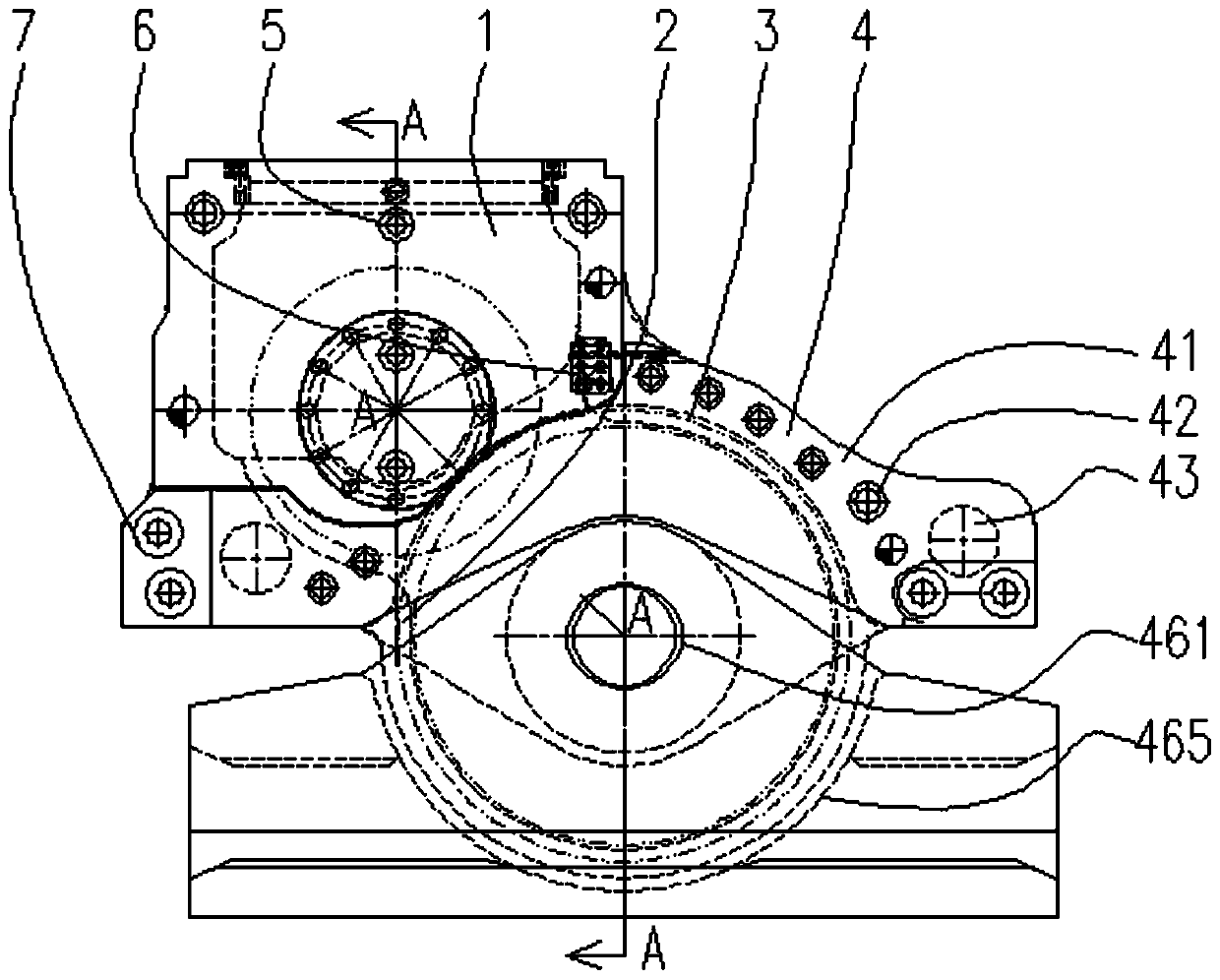
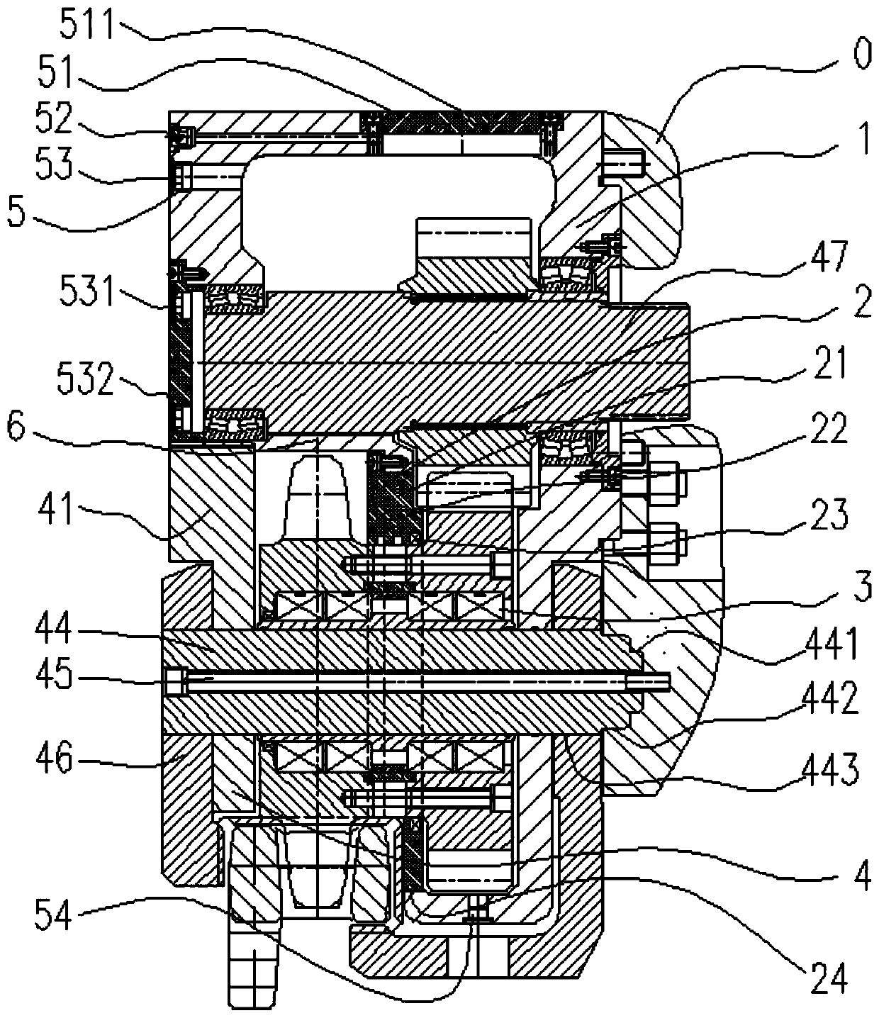
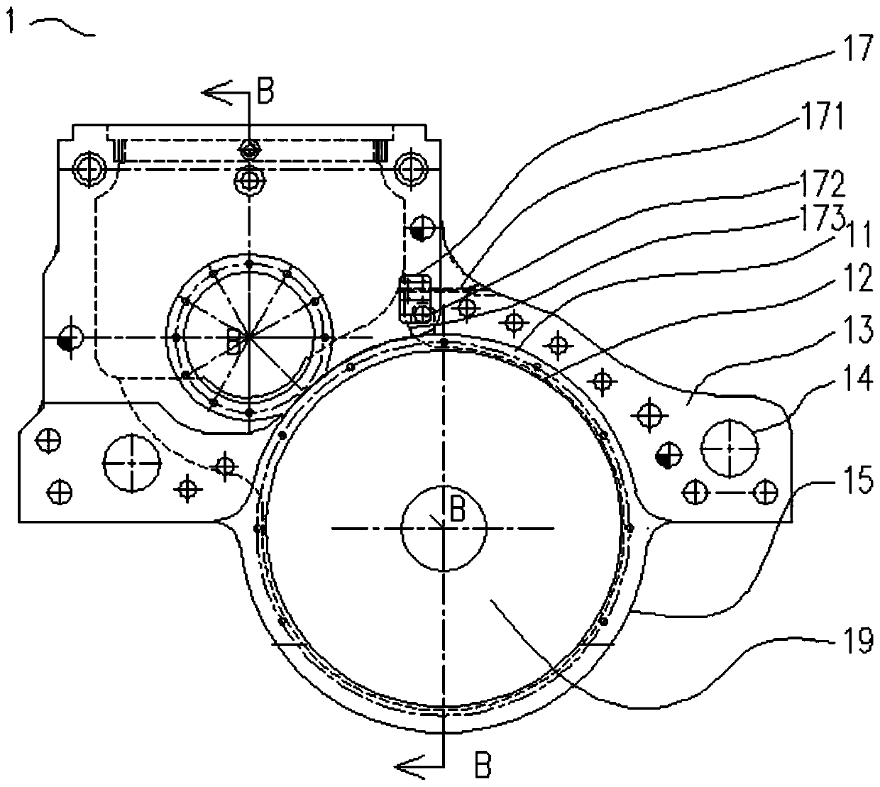
[0040] The invention discloses a walking part with a sub-cavity structure, such as Figure 1-13 As shown, it includes a housing 1 , a drive shaft 471 , a drive gear 473 , a driven gear 36 , a road wheel 37 , a guide shoe 46 and a connecting plate 41 . The housing is provided with an oil pool, the upper part of the connecting plate 41 is detachably fixed on the housing, and the lower part of the connecting plate and the lower front side wall of the oil pool form an open chamber. The drive shaft 471 is supported on the housing through two sets of front and rear bearings 472, and the drive gear is fixedly mounted on the drive shaft. The driving gear 473 is externally meshed with the driven gear 36 . The traveling wheel 37 and the driven gear 36 are coaxially fixed, and one after the other is rotatably connected to the same support shaft 44 via a bearing 39 . The support shaft runs through the connecting ear hole 413 of the connecting plate and the front and rear side walls of t...
PUM
 Abstract
Description
Claims
Application Information