

Counter-flow axial energy dissipation valve
A counter-flow, axial technology, applied in the direction of the valve's energy-absorbing device, valve lift, valve details, etc., can solve problems such as paddy field erosion, and achieve the effect of low cost and simple structure
- Summary
- Abstract
- Description
- Claims
- Application Information
AI Technical Summary
Problems solved by technology
Method used
Image

Examples
specific Embodiment approach 1
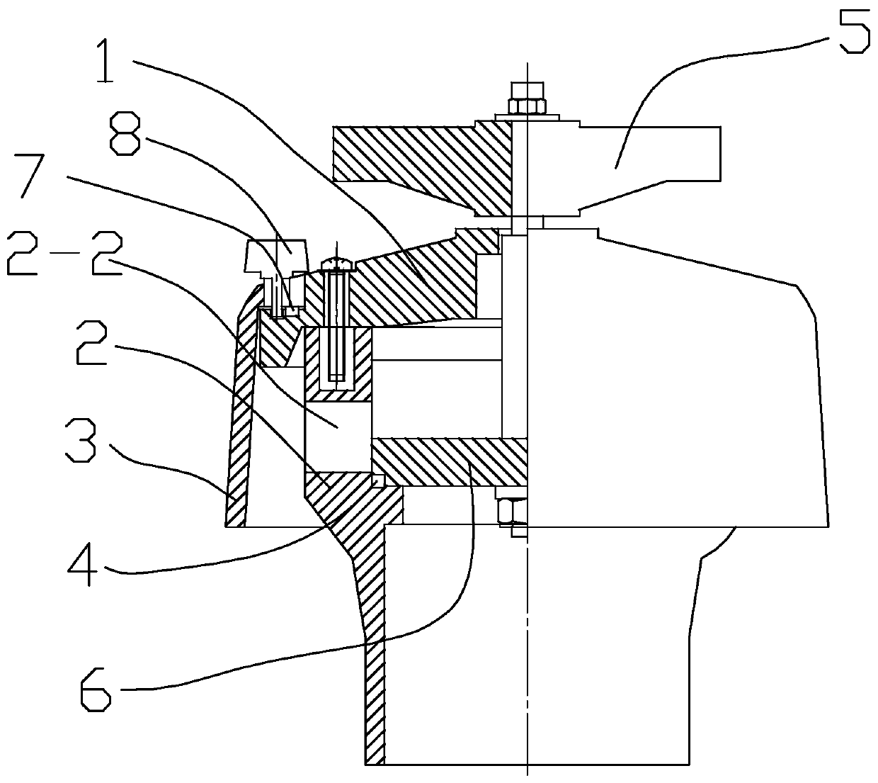
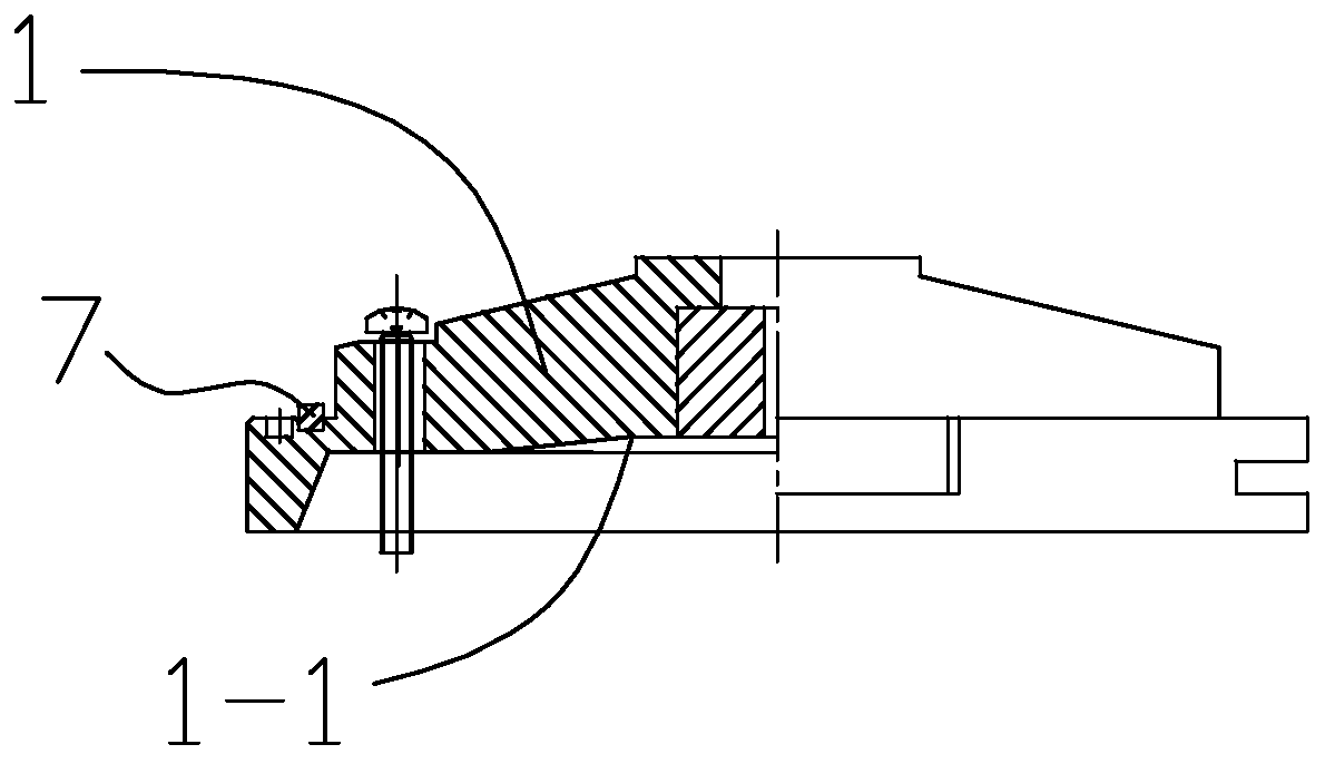
[0017] Specific implementation mode one: combine Figure 1-Figure 4 To illustrate this embodiment, this embodiment includes a valve cover 1, a valve body 2, a guide sleeve 3, a first sealing ring 4, a hand wheel 5, a valve plate 6, a second sealing ring 7 and fasteners 8;
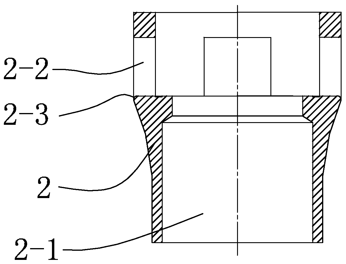
[0018] The valve body 2 is provided with a water inlet 2-1 and a water outlet 2-2, the direction of the water inlet 2-1 on the valve body 2 is perpendicular to the direction of the water outlet 2-2, and the valve plate 6 is arranged in the valve body 2 The water inlet 2-1, and the first sealing ring 4 is provided between the valve plate 6 and the valve body 2, the valve cover 1 and the valve body 2 are fixed together, the handwheel 5 is connected with the valve cover through a screw rod, and the screw rod and the valve body The valve plate 6 is fixed so that the valve plate 6 can move along the direction of the water inlet 2-1 of the valve body 2, and the guide sleeve 3 and the valve cover 1 are sealed by t...
specific Embodiment approach 2
[0020] Embodiment 2: The flow area of the water outlet 2-2 of the valve body 2 in this embodiment is larger than the flow area of the water inlet 2-1.
[0021] Other compositions and connections are the same as in the first embodiment.
specific Embodiment approach 3
[0022] Embodiment 3: The flow area of the water outlet 2-2 of the valve body 2 in this embodiment is 23% larger than the flow area of the water inlet 2-1.
[0023] Such setting increases the ability of water discharge, and ensures that the water has a certain kinetic energy to be ejected from the present invention, and also ensures that the paddy field will not be washed away due to excessive kinetic energy of the water.
[0024] Other compositions and connections are the same as those in the second embodiment.
PUM
 Abstract
Description
Claims
Application Information