
Power electronic transformer structure

A technology of power electronics and transformers, which is applied in the direction of transformers, fixed transformers, electrical component structure associations, etc., can solve the problems of transformers with limited functions and inability to provide functions, and achieve the effect of small number of joints, compact structure, and convenient maintenance

Pending Publication Date: 2019-08-23
GLOBAL ENERGY INTERCONNECTION RES INST CO LTD
View PDF0 Cites 0 Cited by
  • Summary
  • Abstract
  • Description
  • Claims
  • Application Information

AI Technical Summary

Problems solved by technology

[0002] With the continuous development of modern power grids, more and more distributed power generation systems and distributed energy storage systems need to be connected to the power grid. When new energy power generation systems are connected to the grid, interface equipment is required to provide multi-level voltage adjustment and AC-DC intercommunication conversion. , intelligent energy management and other functions, while traditional transformers have limited functions and cannot provide the above functions

Method used

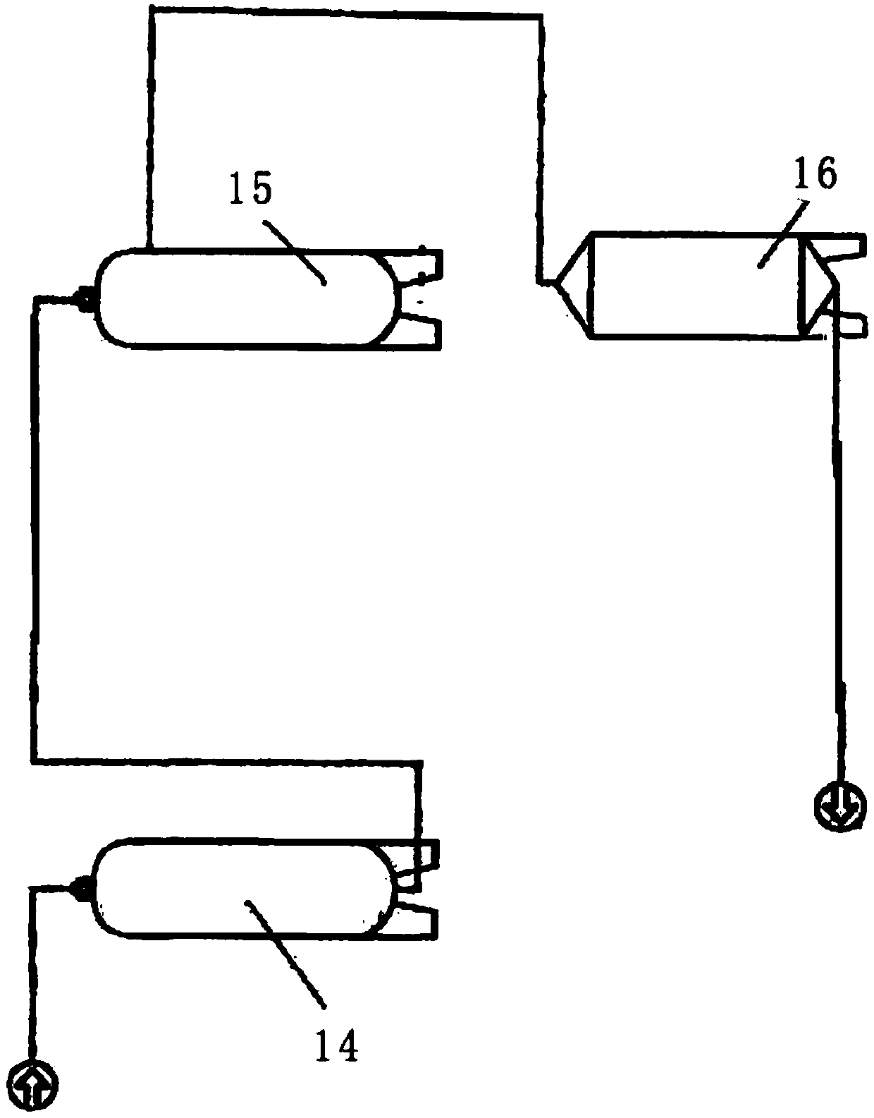

Image

  • Power electronic transformer structure
  • Power electronic transformer structure
  • Power electronic transformer structure

Examples


Embodiment Construction

[0034] In order to better understand the present invention, the technical solution of the present invention will be further described in detail below in conjunction with the accompanying drawings.

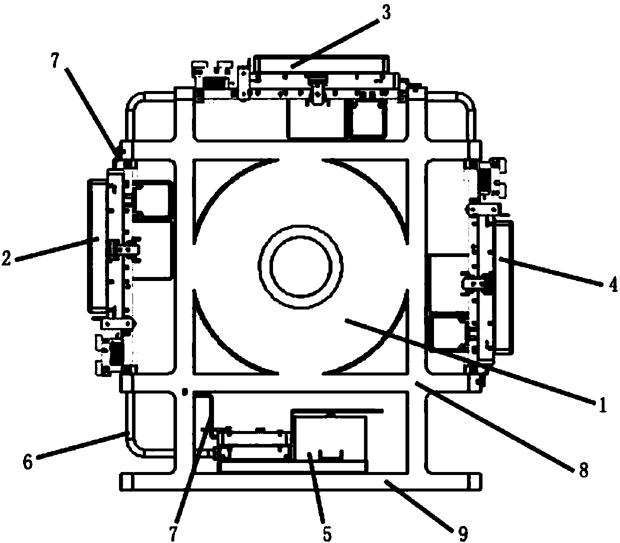
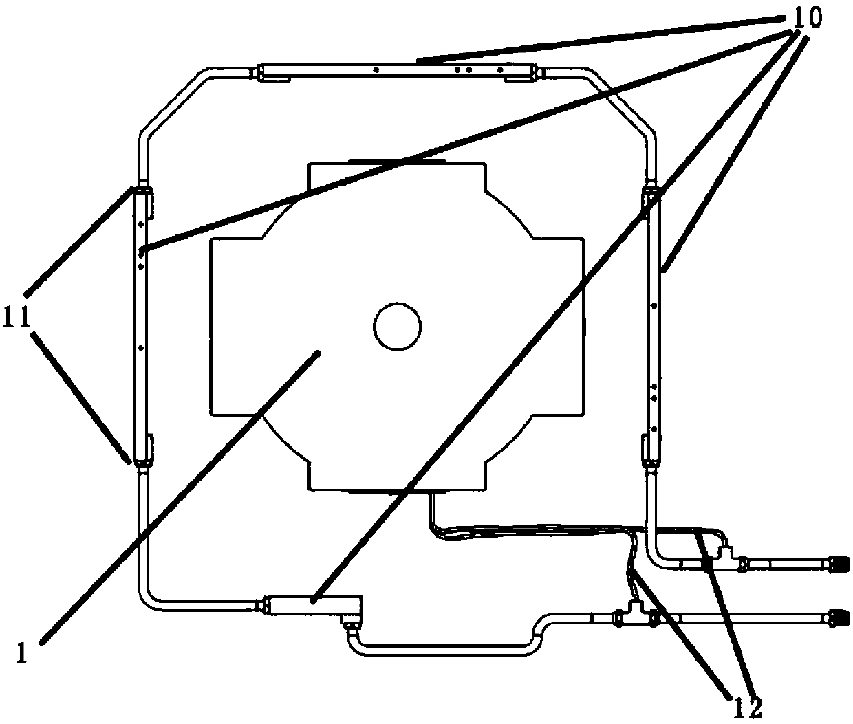
[0035] Such as Figure 1 to Figure 2 As shown, the transformer structure provided by the present invention includes: a support 8, a high-frequency transformer 1, a base 9, a high-voltage side module and a low-voltage side module 5 cooling circuits, and the high-voltage side modules are respectively located on the support 8 The front, top and rear of the frame; the low-voltage side module 5 is located at the bottom of the support 8; the high-frequency transformer 1 is located in the middle of the support 8; the support 8 and the base 9 are made of epoxy materials, The bracket 8 and the base 9 are machined from epoxy laminates; the transformer structure is a ring design, and the load support and insulation barrier are reasonably designed to ensure that the high-voltage side modules a...


PUM


Abstract

The invention relates to a power electronic transformer structure. The power electronic transformer structure comprises a support, a high-frequency transformer, a base, high-voltage modules and a low-voltage module. The high-voltage modules are respectively located at the front portion, the top portion and the rear portion of the support; the low-voltage module is located at the bottom portion ofthe support; and the high-frequency transformer is located at the middle portion of the support. The support employed by the transformer structure is an epoxy support, the support is internally provided with the high-frequency transformer, the high-voltage modules and the low-voltage module are arranged at the outer portion of the support so that the transformer structure is more compact, uniform,and the functional structure has the uniqueness and innovation;; further, the support is the epoxy support so that the problems that the epoxy resin is difficult to solidify and form after pouring and the deformation is difficult to guarantee due to the fact that the dead weight of the iron core and the coil of the high-frequency transformer is heavy are solved; and moreover, the insulation requirement of the whole structure of the power electronic transformer is guaranteed, and the yield of products is greatly improved.

Description

technical field [0001] The invention relates to a transformer structure, in particular to a power electronic transformer structure. Background technique [0002] With the continuous development of modern power grids, more and more distributed power generation systems and distributed energy storage systems need to be connected to the power grid. When new energy power generation systems are connected to the grid, interface equipment is required to provide multi-level voltage adjustment and AC-DC intercommunication conversion. , intelligent energy management and other functions, while the traditional transformer has limited functions and cannot provide the above functions. Contents of the invention [0003] In order to solve the above-mentioned deficiencies in the prior art, the present invention provides a power electronic transformer structure. [0004] The technical solution provided by the present invention is: a power electronic transformer structure, the transformer st...

Claims


Application Information

Patent Timeline
Patent Type & Authority Applications(China)
IPC IPC(8): H01F27/00H01F27/16H01F27/22H01F27/28H01F27/40
CPCH01F27/00H01F27/28H01F27/16H01F27/40H01F27/22H01F27/06H01F30/12
Inventor 邓占锋石秋雨苏铁山康伟乔光尧曾洪涛
Owner GLOBAL ENERGY INTERCONNECTION RES INST CO LTD
Learn More