Integrated structure of magnetic element

A technology of magnetic components and limit structures, which is applied in the direction of electrical components, transformer/inductor cores, transformer/inductor components, etc., can solve the problems of difficult welding, time-consuming and laborious, etc., and achieve compact structure and reduce welding Effect of Difficulty, High Power Density

Pending Publication Date: 2019-08-23
SHENZHEN VMAX NEW ENERGY CO LTD
View PDF0 Cites 0 Cited by
  • Summary
  • Abstract
  • Description
  • Claims
  • Application Information

AI Technical Summary

Problems solved by technology

[0003] The invention provides an integrated structure of magnetic elements, which solves the problem of difficult and time-consuming welding of magnetic elements of switching power supplies in the prior art

Method used


Image

  • Integrated structure of magnetic element
  • Integrated structure of magnetic element
  • Integrated structure of magnetic element

Examples


Embodiment Construction

[0018] The principle and structure of the present invention will be described in detail below in conjunction with the drawings and embodiments.

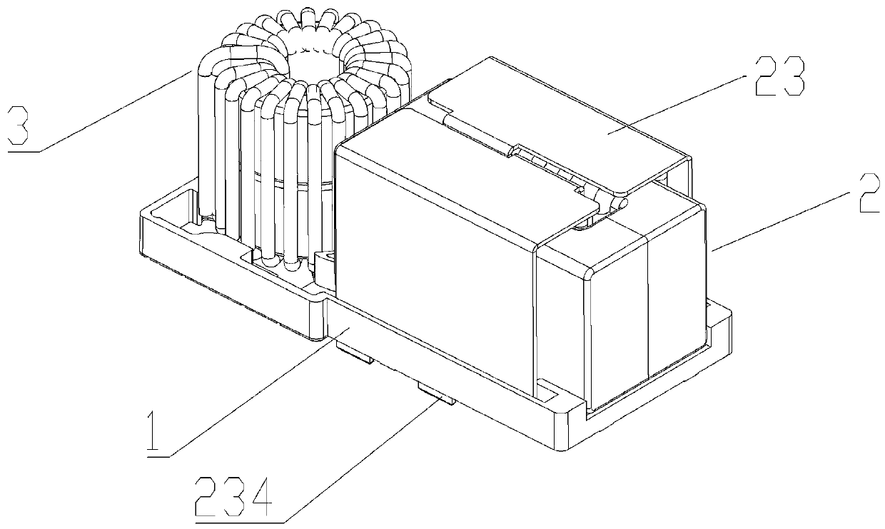
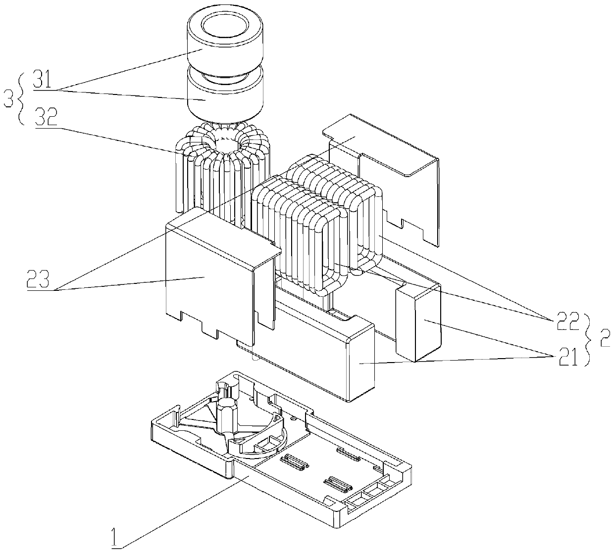
[0019] The present invention proposes an integrated structure of magnetic components, such as figure 1 and 2 As shown, the integrated structure of the magnetic element in the present invention includes a base 1 , a first magnetic element 2 and a second magnetic element 3 .

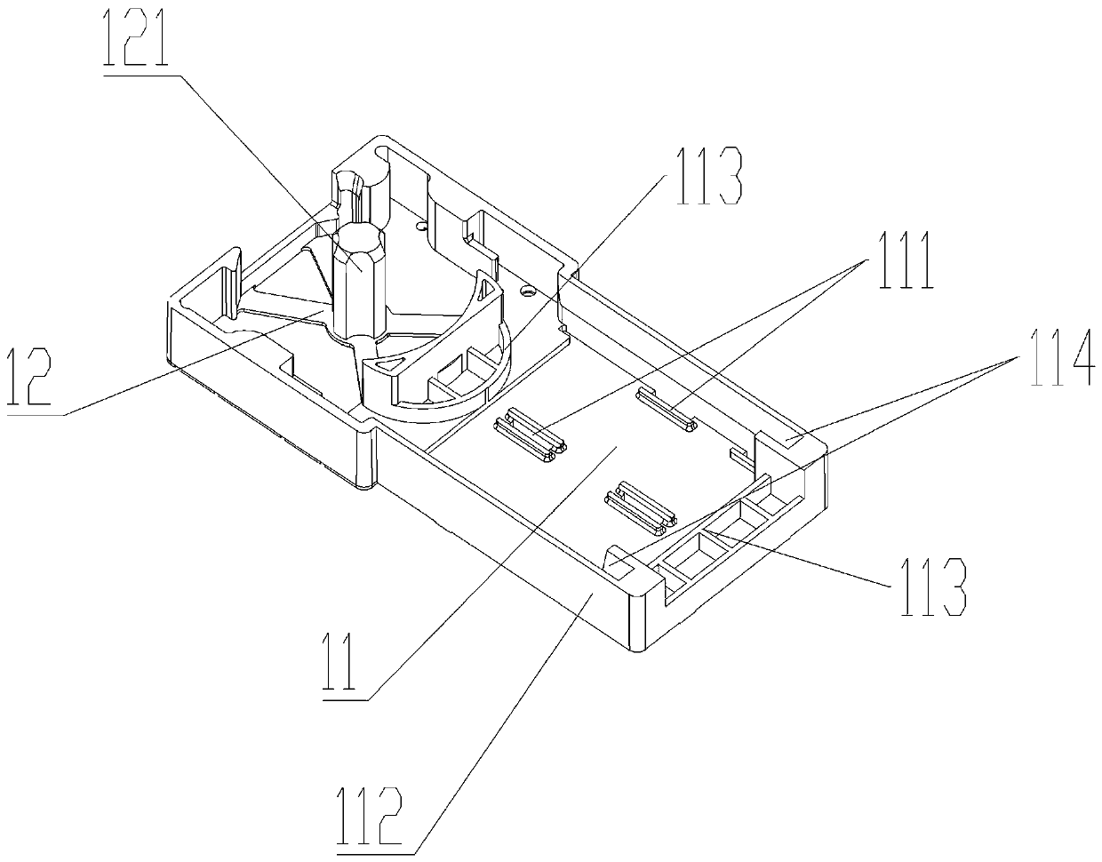
[0020] like image 3 As shown, the base 1 includes a first mounting portion 11 and a second mounting portion 12 , wherein the first mounting portion 11 is used for mounting the first magnetic element 2 , and the second mounting portion 12 is used for mounting the second magnetic element 3 .

[0021] Specifically, in one embodiment, the first magnetic element 2 is a transformer, the first magnetic element 2 specifically includes a first magnetic core 21, two first magnetic cores 21 are provided, and the first magnetic core 21 is C-shaped, The C-shaped first mag...


PUM


Abstract

The invention discloses an integrated structure of a magnetic element. The structure comprises a base which comprises a first mounting part and a second mounting part, wherein a first magnetic elementis mounted on the first mounting part, and a second magnetic element is mounted on the second mounting part, and then the base provided with the first magnetic element and the second magnetic elementis directly welded on a PCB through the welding pins, so that the welding of each magnetic element is not needed, the welding difficulty of the magnetic elements is greatly reduced, and the time andthe labor are saved. Meanwhile, the first magnetic element and the second magnetic element are compact in structure, thereby saving the welding area, and meeting the demands for high power density.

Description

technical field [0001] The invention relates to electromagnetic elements, in particular to an integrated structure of magnetic elements. Background technique [0002] With the requirement of high power density power conversion power supply, the volume of magnetic components is required to be more miniaturized, especially in the field of new energy such as electric vehicle chargers. In a complete switching power supply, at least one inductor and at least one transformer are often required to achieve the purpose of multiple outputs. The inductor and transformer in the traditional switching power supply are independent components, which need to be welded separately in the switching power supply. Due to the small size of these magnetic components, it is difficult to weld, and the welding is time-consuming and laborious; at the same time , The area occupied by separate welding is large, which limits the demand for high power density. Contents of the invention [0003] The inv...

Claims


Application Information

Patent Timeline
IPC IPC(8): H01F27/06H01F27/24H01F27/26H01F27/02
CPCH01F27/06H01F27/24H01F27/266H01F27/02H01F2027/065
Inventor 刘钧冯颖盈姚顺罗耀文
Owner SHENZHEN VMAX NEW ENERGY CO LTD
Why Eureka
Try Eureka