Battery cell winding device, battery cell production method and power battery

A technology of a winding device and a production method, applied in the field of battery production and manufacturing

Active Publication Date: 2019-08-23
JIANGSU ZENIO NEW ENERGY BATTERY TECH CO LTD
View PDF6 Cites 4 Cited by
  • Summary
  • Abstract
  • Description
  • Claims
  • Application Information

AI Technical Summary

Problems solved by technology

[0004] Existing coatings are generally coated continuously and uniformly on the separator, but coatings with uniform thickness cannot meet the needs of batteries with different performance requirements

Method used


Image

  • Battery cell winding device, battery cell production method and power battery
  • Battery cell winding device, battery cell production method and power battery
  • Battery cell winding device, battery cell production method and power battery

Examples


Embodiment 1

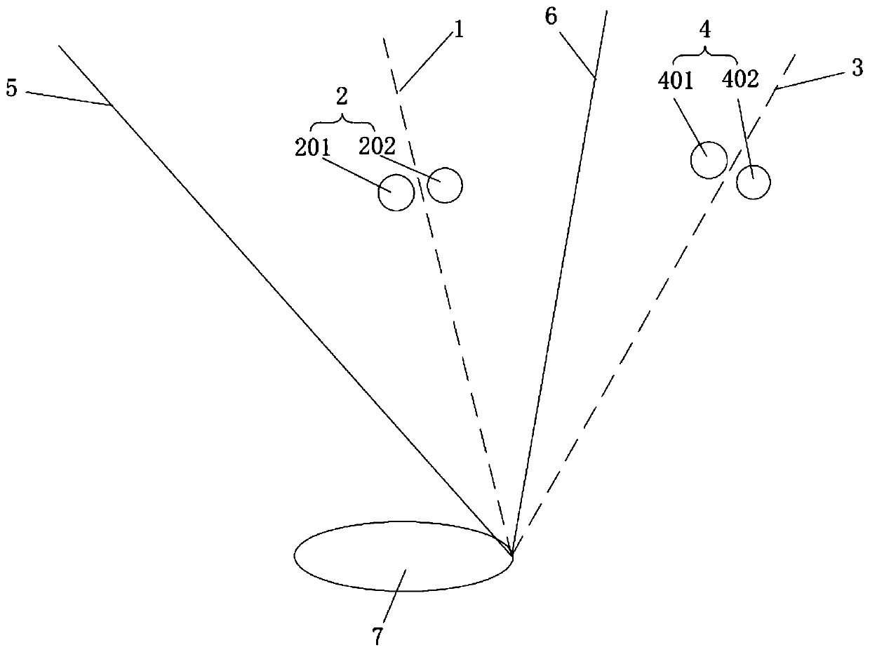
[0057] This embodiment provides a battery winding device, such as figure 1 As shown, the cell winding device includes a first coating bonding roller group 2 , a second coating bonding roller group 4 and a winding needle 7 . Wherein, the first coating adhesive roller group 2 is used to modify the thickness of the inner adhesive coating on the inner diaphragm 1, and the second coating adhesive roller group 4 is used to modify the thickness of the outer adhesive coating on the outer diaphragm 3, after modification The final inner diaphragm 1 and outer diaphragm 3 are laminated with positive electrode sheet 5 and negative electrode sheet 6 to form an electric chip. One end of the electric chip is placed at the winding needle 7, and the winding needle 7 rotates under the drive of the power source, so that the stacked electric chips are wound on the winding needle 7 along the circumferential direction of the winding needle 7 to form a battery cell 8.

[0058] In this embodiment, th...

Embodiment 2

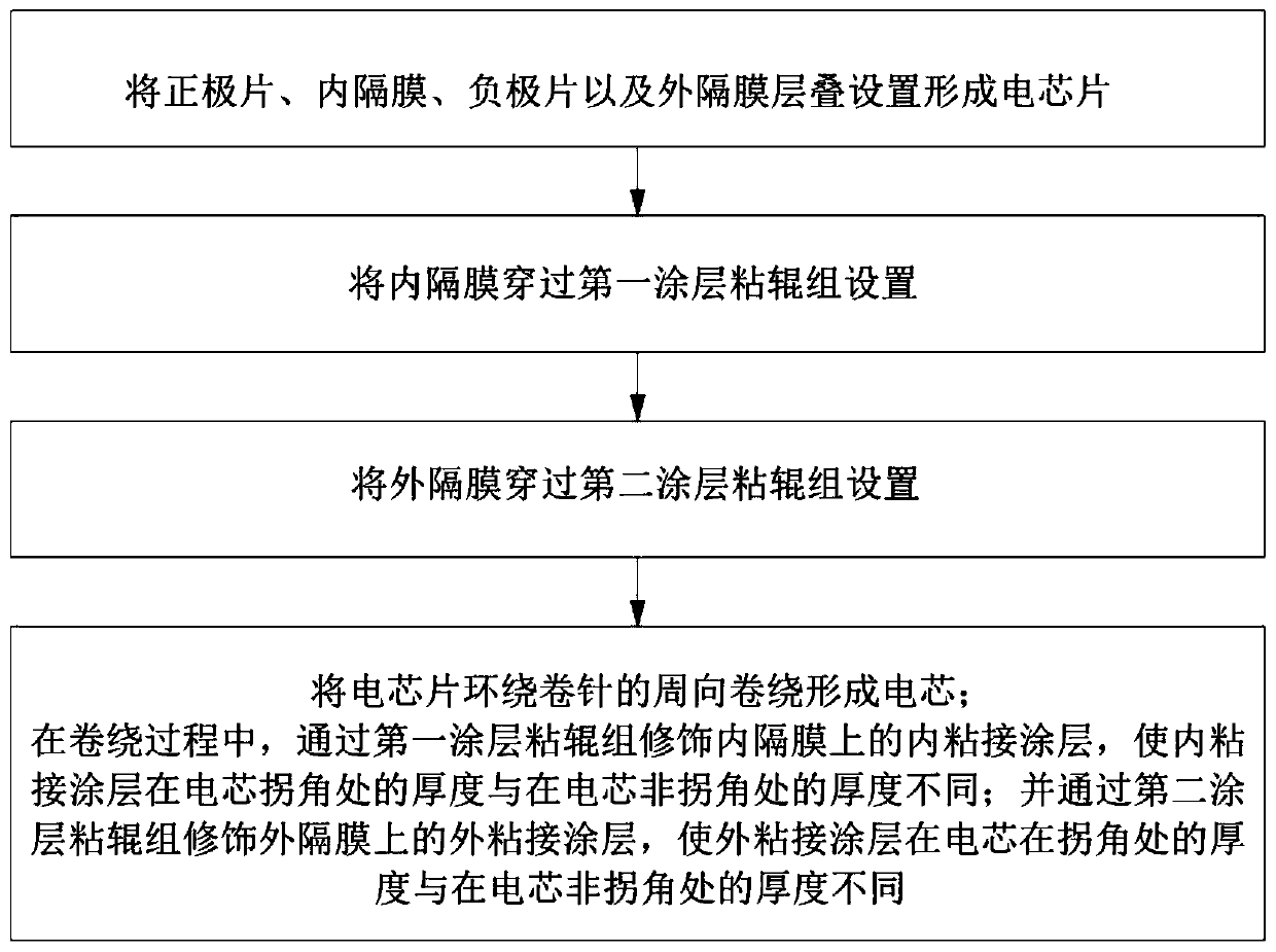
[0064] On the basis of Embodiment 1, this embodiment also provides a battery production method, such as figure 2 As shown, it specifically includes the following steps:

[0065] The positive electrode sheet 5, the inner diaphragm 1, the negative electrode sheet 6 and the outer diaphragm 3 are stacked to form an electric chip;

[0066] Setting the inner diaphragm 1 through the first coating sticky roller group 2;

[0067] Setting the outer diaphragm 3 through the second coating sticky roller group 4;

[0068] The electric chip is wound around the circumference of the winding needle 7 to form an electric core 8; during the winding process, the inner adhesive coating on the inner diaphragm 1 is modified by the first coating adhesive roller group 2, so that the inner adhesive coating The thickness at the corner of the electric core 8 is different from the thickness at the non-corner of the electric core 8; The thickness at the corners of the core 8 is different from the thickn...

Embodiment 3

[0082] On the basis of Embodiment 1 and Embodiment 2, this embodiment also provides a power battery. The power battery is a lithium-ion battery, specifically including a casing and an electric cell 8 placed in the casing. The electric cell 8 includes sequentially stacked The positive electrode sheet 5, the inner diaphragm 1, the negative electrode sheet 6 and the outer diaphragm 3 are wound, and the inner diaphragm 1 is provided with an inner adhesive coating, and the thickness of the inner adhesive coating at the corner of the electric core 8 is the same as that of the inner adhesive coating at the corner of the electric core 8. The thickness of the non-corner is different, and the outer diaphragm 3 is provided with an outer adhesive coating, and the thickness of the outer adhesive coating at the corner of the battery cell 8 is different from that at the non-corner of the battery cell 8, which can improve the battery performance in a targeted manner. performance to form a powe...


PUM


Abstract

The invention discloses a battery cell winding device, a battery cell production method and a power battery, and belongs to the technical field of battery production and manufacturing. The battery cell winding device provided by the invention comprises a first coating adhesive roller group, a second coating adhesive roller group and a winding needle, wherein the first coating adhesive roller groupcan modify the thickness of an inner adhesive coating on an inner diaphragm, the second coating adhesive roller group can modify the thickness of an outer adhesive coating on an outer diaphragm, andthe winding needle can wind a battery cell piece to form a battery cell. Through the arrangement of the first coating adhesive roller group, the thickness of the inner adhesive coating on the inner diaphragm can be modified before the battery cell is wound, thereby forming the inner adhesive coating with the uneven thickness on the inner diaphragm; through the arrangement of the second coating bonding roller group, the thickness of the outer adhesive coating on the outer diaphragm can be modified before the battery cell is wound, thereby forming the outer adhesive coating with the uneven thickness can be formed on the outer diaphragm. The battery cell wound by the battery cell winding device can meet the demands of various power batteries with different performance requirements, and is high in flexibility and wide in application range.

Description

technical field [0001] The invention relates to the technical field of battery production and manufacturing, in particular to a battery winding device, a battery production method and a power battery. Background technique [0002] With the increasingly serious energy crisis and environmental pollution around the world, green and sustainable energy has gradually become the goal pursued by the world. Lithium-ion batteries have become an energy source for electronic products and electric vehicles due to their high energy density, long cycle life, low self-discharge, and environmental friendliness. [0003] Lithium-ion battery packs generally increase the overall energy density by increasing the capacity of single cells and reducing the number of cells in a group. Increasing the capacity of a single cell leads to an increase in the number of winding layers of the cell, which rapidly increases the internal stress of the pole piece expansion of the battery during charging and dis...

Claims


Application Information

Patent Timeline
Patent Type & Authority Applications(China)
IPC IPC(8): H01M10/0525H01M10/04H01M10/0587
CPCH01M10/0431H01M10/0525H01M10/0587Y02E60/10Y02P70/50
Inventor 武冬冬袁威
Owner JIANGSU ZENIO NEW ENERGY BATTERY TECH CO LTD
Why Eureka
Try Eureka