A magnetic gear device with metal foil

A technology of metal flakes and magnetic gears, applied in the field of magnetic gears, can solve problems such as pitting, broken teeth, and gluing, and achieve the effects of reducing speed fluctuations, increasing stability, and reducing fluctuations

Active Publication Date: 2020-12-04
日照新睿招商发展有限公司
View PDF5 Cites 0 Cited by
  • Summary
  • Abstract
  • Description
  • Claims
  • Application Information

AI Technical Summary

Problems solved by technology

[0003] However, after long-term work and use of this kind of gear, it is prone to problems such as pitting, gluing, wear, and broken teeth, and is prone to damage. With the continuous development of science and technology, a magnetic gear has appeared at present. The magnetic gear has a simple structure. , no friction, no oil, less maintenance and automatic overload protection, it is a more ideal transmission equipment than traditional gears
[0004] The existing magnetic gears generally cannot meet the requirement that the instantaneous speed always maintains the transmission ratio during the transmission process, and the fluctuation of the rotational speed roughly causes the fluctuation of the output torque to be large, which in turn affects the stable transmission of the magnetic gear

Method used


Image

  • A magnetic gear device with metal foil
  • A magnetic gear device with metal foil
  • A magnetic gear device with metal foil

Examples


Embodiment Construction

[0024] The following will clearly and completely describe the technical solutions in the embodiments of the present invention with reference to the accompanying drawings in the embodiments of the present invention. Obviously, the described embodiments are only some, not all, embodiments of the present invention.

[0025] In describing the present invention, it should be understood that the terms "upper", "lower", "front", "rear", "left", "right", "top", "bottom", "inner", " The orientation or positional relationship indicated by "outside", etc. is based on the orientation or positional relationship shown in the drawings, and is only for the convenience of describing the present invention and simplifying the description, rather than indicating or implying that the referred device or element must have a specific orientation, so as to Specific orientation configurations and operations, therefore, are not to be construed as limitations on the invention.

[0026] refer to Figure ...


PUM


Abstract

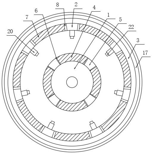
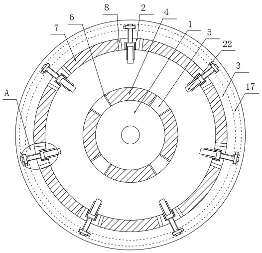
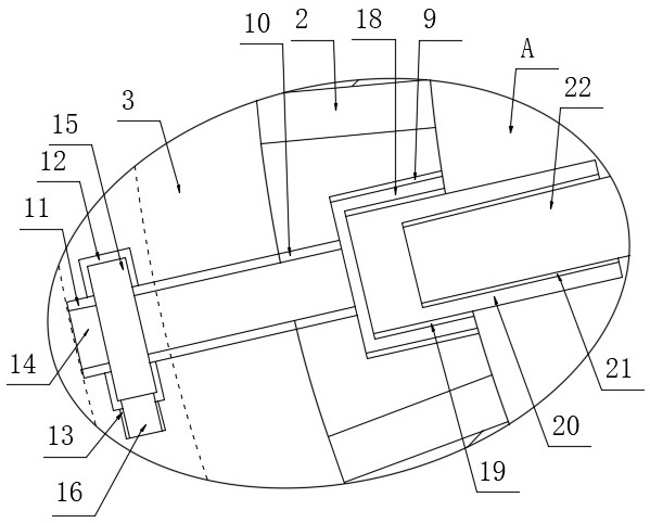
The invention discloses a magnetic gear device with a metal foil. The magnetic gear device includes an inner yoke, an outer rotor, an outer yoke and an inner rotor, wherein multiple inner rotating permanent magnets are mounted on the inner rotor, multiple outer rotating permanent magnets are mounted on the outer rotor, multiple first mounting slots and multiple connecting slots are defined on theouter rotor, the first mounting slots are in communication with the corresponding connecting slots, a mounting seat is engaged on each of the first mounting slots, and the first mounting slots and themounting seats are all circular. The magnetic gear device is advantaged in that a magnetic gear with the metal foil can reduce fluctuation of the rotational speed of the outer rotor in the transmission process of the inner rotor, stability of the rotational speed is enhanced, fluctuation of the output torque is reduced, the magnitude of the magnetic flux is changed by changing angles between themetal foil and the inner and inner rotating permanent magnets and length, so intensity of magnetic induction is changed, and finally intensity of the magnetic field is enhanced to some extent.

Description

technical field [0001] The invention relates to the technical field of magnetic gears, in particular to a magnetic gear device with metal flakes. Background technique [0002] Gear transmission is the most widely used form of transmission in mechanical transmission. It is mainly used to transmit the rotary motion between two shafts. Traditional disc-mounted gears are integral gears, such as spur gears, helical gears and other different gears. , are integral gears; [0003] However, after long-term work and use of this kind of gear, it is prone to problems such as pitting, gluing, wear, and broken teeth, and is prone to damage. With the continuous development of science and technology, a magnetic gear has appeared at present. The magnetic gear has a simple structure. , no friction, no oil, less maintenance and automatic overload protection, it is a more ideal transmission equipment than traditional gears. [0004] The existing magnetic gears generally cannot satisfy the rel...

Claims


Application Information

Patent Timeline
Patent Type & Authority Patents(China)
IPC IPC(8): H02K49/10
CPCH02K49/102H02K49/106
Inventor 路运福周峰王云楠
Owner 日照新睿招商发展有限公司
Why Eureka
Try Eureka