an on-chip encoder

An encoder and coding technology, applied in the field of on-chip encoders, can solve the problems of difficult and high-speed modulation, slow thermo-optic effect, and low modulation efficiency.

Active Publication Date: 2020-08-04
INST OF SEMICONDUCTORS - CHINESE ACAD OF SCI
View PDF12 Cites 0 Cited by
  • Summary
  • Abstract
  • Description
  • Claims
  • Application Information

AI Technical Summary

Problems solved by technology

So people began to try to integrate the devices and subsystems required by the quantum key distribution device on the chip. For the polarization BB84 protocol quantum key distribution, the technical core is to prepare different polarization states of light. However, for silicon materials, because there is no The linear electro-optic effect achieves phase delay by modulating the refractive index, mainly relying on the thermo-optic effect and the plasma dispersion effect. The thermo-optic effect is slow and it is difficult to achieve high-speed modulation, while the plasma dispersion effect is fast, but the modulation efficiency is relatively low. , leading to phase delay difficulties and introducing additional losses, making it difficult to implement a high-speed on-chip polarization encoder

Method used


Image

  • an on-chip encoder
  • an on-chip encoder

Examples


Embodiment Construction

[0019] In order to make the object, technical solution and advantages of the present invention clearer, the present invention will be described in further detail below in conjunction with specific embodiments and with reference to the accompanying drawings.

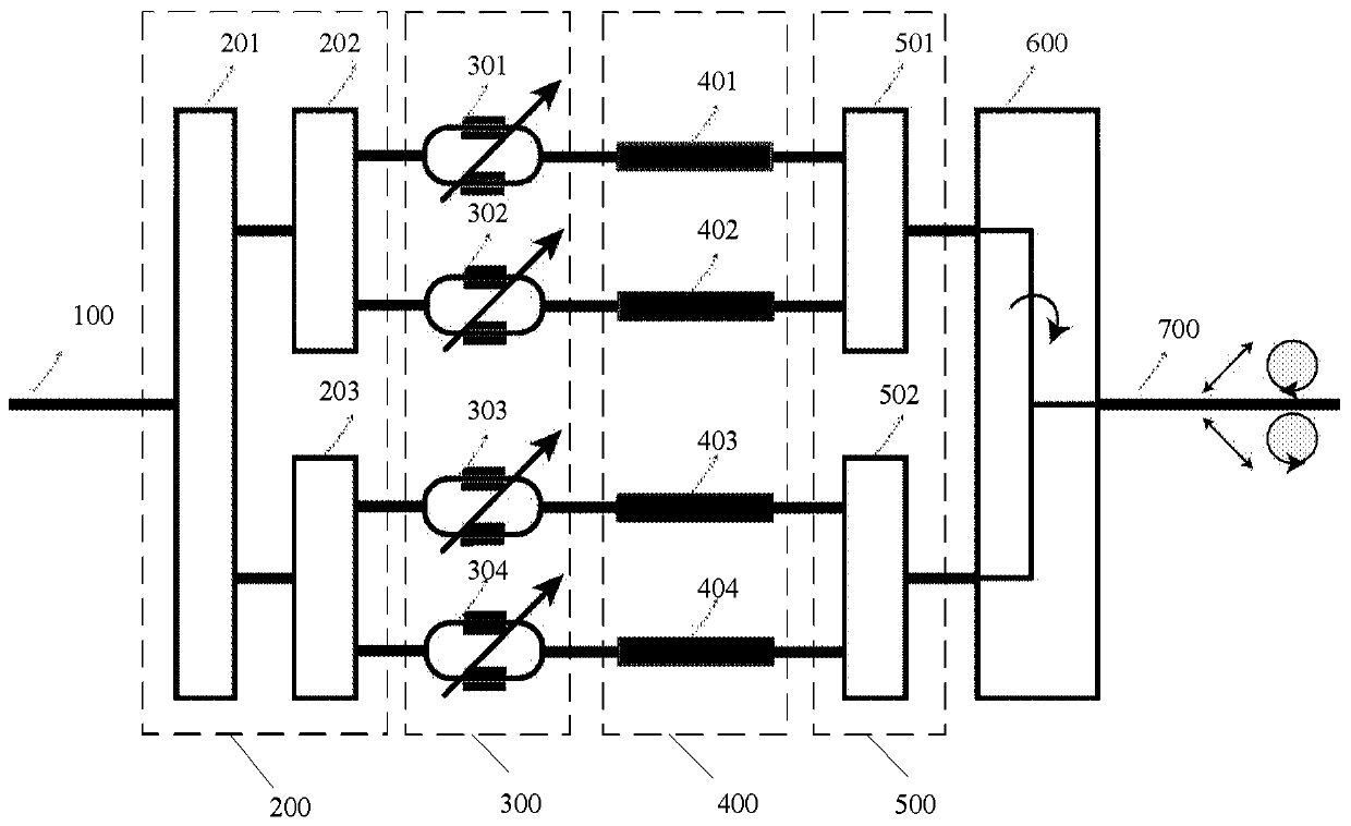
[0020] The present invention provides an on-chip encoder for encoding signal light, see figure 1 , including: an input waveguide 100 for inputting signal light; a 1×2 beam splitter 200 including a first beam splitter 201, a second beam splitter 202 and a third beam splitter 203, wherein the first An optical beam splitter 201 divides the signal light into two beams and sends them to the second optical beam splitter 202 and the third optical beam splitter 203 respectively, and then the second optical beam splitter 202 and the third optical beam splitter 203 further receive The incoming signal light is divided into two beams of signal light respectively; the signal light switch 300 is arranged behind the second light beam sp...


PUM


Abstract

An on-chip encoder comprises: an input waveguide (100); a 1 * 2 light beam splitter (200) used for splitting the received signal light into two beams of signal light respectively; a signal light switch (300) used for realizing passing and blocking of the signal light; a phase bias modulator (400) used for adjusting the phases of the four beams of signal light; 1 * 2 light beam combiners (500), comprising a first light beam combiner (501) and a second light beam combiner (502); a polarization rotation beam combiner (600) used for receiving the two beams of signal light output by the 1 * 2 lightbeam combiner (500) and rotating one of the two beams of signal light, so that the polarization direction of the rotated signal light is orthogonal to the polarization direction of the other beam ofsignal light, and the rotated signal light and the other beam of signal light are combined into one beam; and output waveguide (700). Four kinds of polarization state signal light are generated through logic combination of the signal light switch (300), the phase bias modulator (400) and the like, and the modulation requirement of polarization BB84 protocol quantum key distribution is exactly met.

Description

technical field [0001] The invention relates to the technical field of quantum communication and integrated optics, in particular to an on-chip encoder. Background technique [0002] The currently recognized quantum key distribution devices are mainly based on traditional discrete optical prisms or fiber optic devices, which are bulky, difficult to integrate, and costly, which is not conducive to large-scale commercialization. With the development of silicon-based photonics, the functions of discrete optical devices can gradually be realized on-chip, which facilitates integration. At the same time, using mature silicon device processing platforms, large-scale and low-cost mass production can be realized. So people began to try to integrate the devices and subsystems required by the quantum key distribution device on the chip. For the polarization BB84 protocol quantum key distribution, the technical core is to prepare different polarization states of light. However, for sili...

Claims


Application Information

Patent Timeline
Patent Type & Authority Patents(China)
IPC IPC(8): H04L9/08
CPCH04L9/0858
Inventor 戴进成杨林张磊
Owner INST OF SEMICONDUCTORS - CHINESE ACAD OF SCI
Why Eureka
Try Eureka