Cable penetrating method and system for low tower cable-stayed bridge

A low-tower cable-stayed bridge and cable threading technology, applied in bridges, bridge parts, bridge construction, etc., can solve the problems of a large number of threading cables and the inability to use cable threading technology, etc., so as to reduce the difficulty of manual operation, reduce construction risks, Ensure the effect of construction quality

Inactive Publication Date: 2019-08-27
CCCC SHEC DONGMENG ENG CO LTD
View PDF4 Cites 5 Cited by
  • Summary
  • Abstract
  • Description
  • Claims
  • Application Information

AI Technical Summary

Problems solved by technology

[0004] Due to the design characteristics of the cable-stayed bridges with low towers, several parallel steel strands need to be threaded in each split tube, and there are several split tube saddles in each main tower, so there are many cables. , cannot use the same cable threading process as other conventional cable-stayed bridge cable-stayed cables

Method used


Image

  • Cable penetrating method and system for low tower cable-stayed bridge

Examples


Embodiment 1

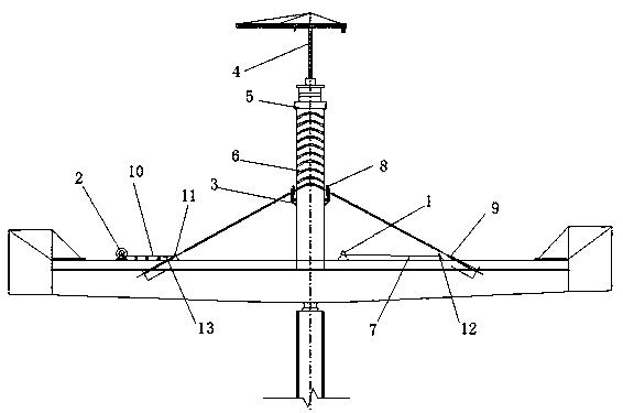
[0044] Refer to attached figure 1 Shown, a kind of low-tower cable-stayed bridge threading method comprises the following steps:

[0045] Step 1: Number the cable saddle 6 of the split pipe and the pre-embedded cable tube 9 of the main beam correspondingly;

[0046] Step 2: Pass the traction rope 7 through the wire splitting pipe saddle 6, connect one end to the winch 1, and connect the other end to the steel strand 10;

[0047] Step 3: start the hoist 1 to rewind the traction rope 7, pass one end of the steel strand 10 through the wire splitting pipe saddle 6, and then install the two ends of the steel strand 10 into the embedded cable tubes 9 on both sides of the main beam;

[0048] Step 4: Repeat steps 1-3 until all steel strands 10 are threaded.

[0049] As a further optimization of the scheme, step 1 includes the following steps:

[0050] Step 1.1: Number the N splitting tube saddles 6 in the main tower 5, numbered 1-N, and mark the number on each splitting tube saddle 6...

Embodiment 2

[0069] Please refer to figure 1 , The difference between this embodiment and Embodiment 1 is that this embodiment provides a rope system applying the method of the embodiment.

[0070] A cable threading system for a cable-stayed bridge with low towers, comprising a hoist 1, a cable reel 2, a cable threading work platform 3 and a hanging tower 4, the hanging tower 4 is arranged on the top of the main tower 5, and the cable threading working platform 3 is arranged on the main tower On the 5th surrounding wall, the winch 1 and the cable reel 2 are respectively placed on the bridge decks on both sides of the main tower 5; it also includes a traction rope 7, an operator 8, and the suspension tower 4 hoists the traction rope 7 to the rope-threading work platform 3, The operator 8 connects one end of the traction rope 7 through the saddle 6 of the wire splitting pipe to the hoist 1, and the other end to the steel strand 10 on the cable reel 2; The steel strand 10 drives and passes t...


PUM


Abstract

The invention provides a cable penetrating method for a low tower cable-stayed bridge. The cable penetrating method comprises the following steps that 1, a sleeve cable saddle and main beam pre-buriedcable pipes are numbered correspondingly; 2, a traction rope penetrates through the sleeve cable saddle, one end of the traction rope is connected with a winch, and the other end of the traction ropeis connected with steel strands; 3, the winch is started to wind the traction rope, and after one ends of the steel strands penetrate through the sleeve cable saddle, the two ends of the steel strands are mounted into the pre-buried cable pipes on the two sides of a main beam correspondingly; and 4, the steps 1 to 3 are repeated until cable penetrating of all the steel strands is completed. Aiming at the situations of large work intensity and large difficulty of traditional manual penetrating of the steel strands, mechanical penetrating of the steel strands is achieved through the traction rope, a cable penetrating device and the winch, and the problem that during manual penetrating of the steel strands, the steel strands are prone to being bent in a sleeve, and consequently cable penetrating is difficult is solved; and by adopting the cable penetrating method, the problems are solved effectively, the time period of the cable penetrating process is shortened, and the cable penetratingdifficulty and the work intensity are lowered.

Description

technical field [0001] The invention relates to the technical field of construction of short-tower cable-stayed bridges, in particular to a cable-passing method and system for short-tower cable-stayed bridges. Background technique [0002] With the development of global bridge construction technology, a low-tower cable-stayed bridge with a span of 100-200m came into being. The rigidity of the continuous girder bridge and the aesthetics of the cable-stayed bridge have the characteristics of economical construction and convenient construction. At present, a large number of bridges in the whole bridge have adopted this design scheme. [0003] The cable-stayed cables of low-tower cable-stayed bridges usually use epoxy-coated parallel steel strand cables. The cable-stayed cables are steered through the saddle of the split-wire tube installed in the main tower, and the outer casing of the split-wire tube is buried in the concrete. Several small steel pipes in the split pipe are s...

Claims


Application Information

Patent Timeline
Patent Type & Authority Applications(China)
IPC IPC(8): E01D21/00E01D19/16
CPCE01D19/16E01D21/00
Inventor 杨红孙国军梁瑞张永华
Owner CCCC SHEC DONGMENG ENG CO LTD
Why Eureka
Try Eureka