An active oil-gas separator

A kind of oil and gas separator, active technology, applied in the direction of engine components, machine/engine, crankcase ventilation, etc., can solve the problems of low oil and gas separation efficiency, deterioration of the environment, poor engine emissions, etc., to increase the separation burden, improve efficiency, Avoid the effect of reducing separation efficiency

Active Publication Date: 2020-07-24
ZHEJIANG GEELY HOLDING (GROUP) CO LTD +1
View PDF3 Cites 0 Cited by
  • Summary
  • Abstract
  • Description
  • Claims
  • Application Information

AI Technical Summary

Problems solved by technology

[0004] The above three oil and gas separators are all passive oil and gas separators. This passive oil and gas separator uses the gas pressure difference of the engine itself. The complete engine oil is brought into the engine for combustion, causing the engine to work roughly, affecting the life of the engine, causing worse engine emissions, deteriorating the environment, and adversely affecting human health

Method used


Image

  • An active oil-gas separator
  • An active oil-gas separator
  • An active oil-gas separator

Examples


Embodiment Construction

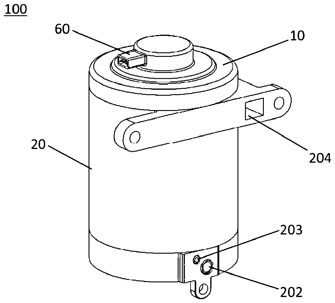
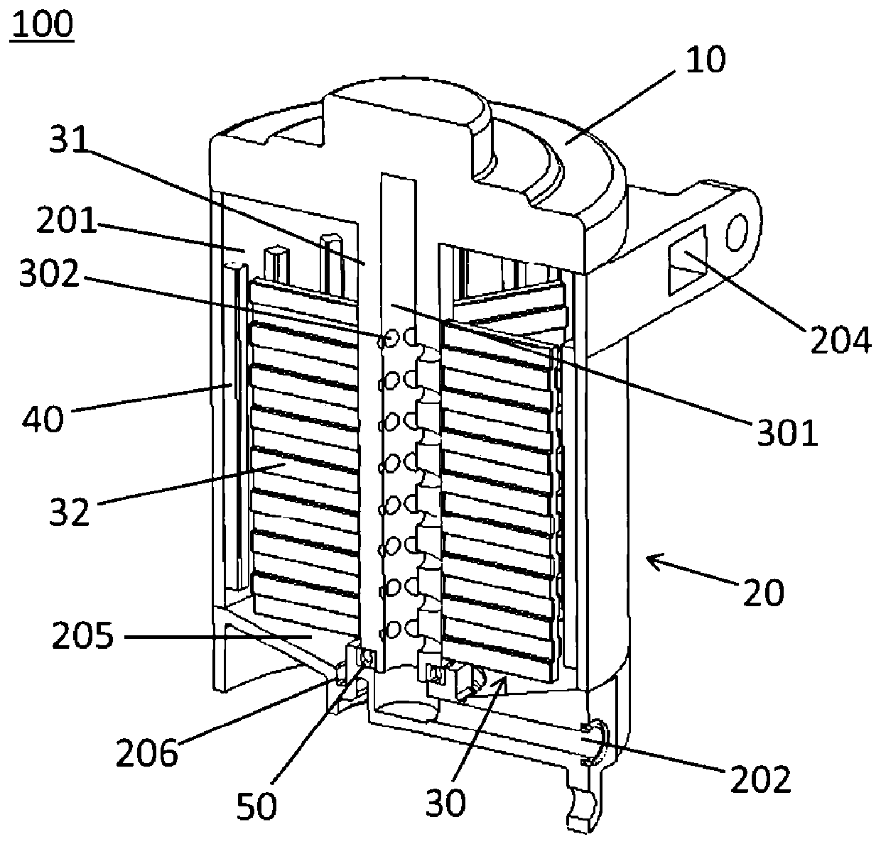
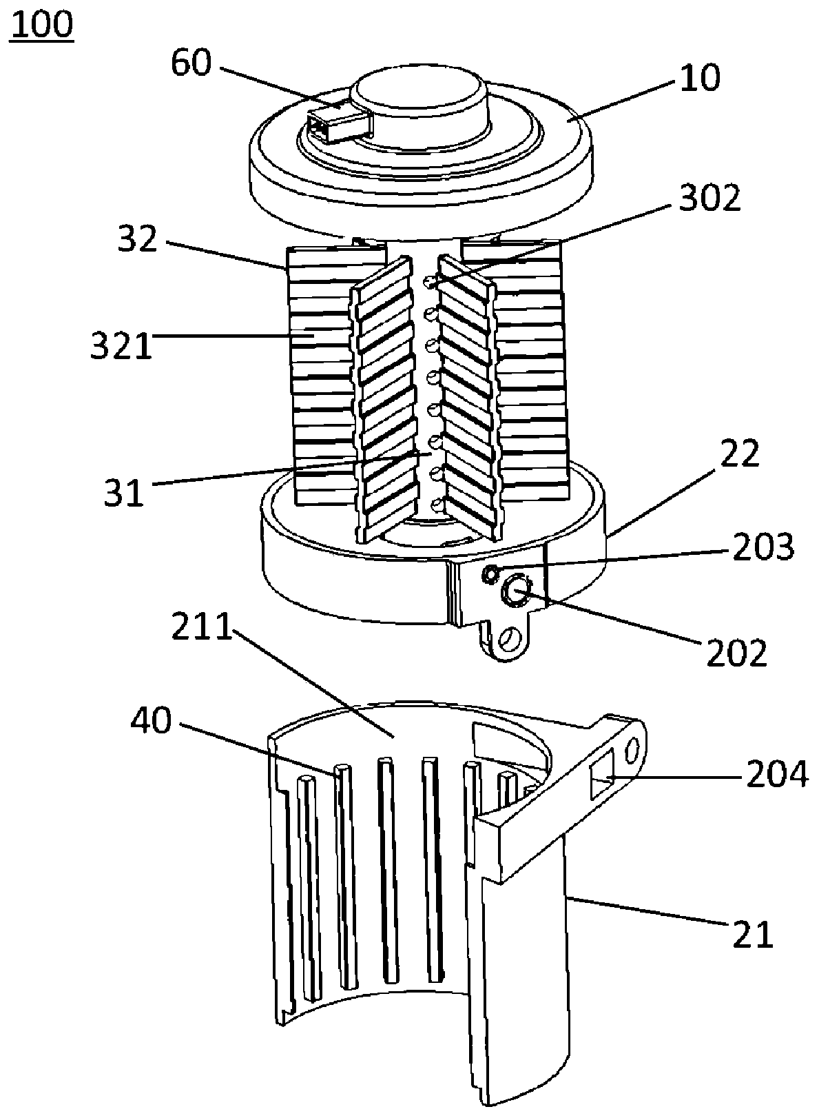
[0035] figure 1 is a schematic structural diagram of an oil-gas separator 100 according to an embodiment of the present invention. figure 2 is a cross-sectional view of an oil-gas separator 100 according to an embodiment of the present invention. Such as figure 1 As shown, the present invention provides an active oil-air separator 100 for separating the exhaust gas of the engine crankcase, and the oil-air separator 100 may generally include a motor 10, a body 20 and a rotating device 30 (see figure 2 ). The motor 10 is used to provide rotational power. Such as figure 2 As shown, the inside of the body 20 is provided with a first cavity 201, and is provided with an oil and gas inlet 202 and an oil return port 203 at the bottom of the body 20 and an air outlet 204 at the top of the body 20. One end of the oil and gas inlet 202 is connected to the engine crankcase The oil return port 203 is used to communicate with the first chamber 201 and the crankcase of the engine, an...


PUM


Abstract

The invention provides an active oil-gas separator, and belongs to the technical field of engines. The active oil-gas separator comprises a motor and a rotating device, wherein the motor comprises a body, a first storing cavity is formed in the body, an oil-gas inlet and an oil return opening located in the bottom of the first storing cavity are formed in the body, one end of the oil-gas inlet communicates with a crankcase of an engine, the oil returning opening is used for communicating with the first storing cavity and the crankcase of the engine, and a gas outlet is used for communicating with the first storing cavity and an air intake system of the engine; and the rotating device is arranged in the first storing cavity and comprises a rotating column and a plurality of blades extendingout of the rotating column in the radial direction, the rotating column is connected with the motor so as to drive the blades to rotate, a second storing cavity communicating with the oil-gas inlet is formed in the rotating column, and a plurality of oil-gas spraying openings communicating with the first storing cavity and the second storing cavity are formed in the side wall of the rotating column. The active oil-gas separator can effectively improve the efficiency of the oil-gas separation.

Description

technical field [0001] The invention relates to the technical field of engines, in particular to an active oil-gas separator. Background technique [0002] Due to the increasingly stringent emission requirements of automobiles, the requirements of engine emissions and crankcase exhaust gas are also increasingly strict. Therefore, in order to meet the requirements of the current environment, the design of the engine crankcase ventilation system has also become diverse and more complicated. [0003] At present, in order to purify the crankcase exhaust gas, passive oil-gas separators are widely used in engines, such as labyrinth oil-gas separators, jet hole-type oil-gas separators and cyclone-type oil-gas separators. The oil and gas in the exhaust gas of the tank are separated, and the separated oil falls back to the crankcase, and the gas participates in the engine intake for combustion. [0004] The above three oil and gas separators are all passive oil and gas separators. T...

Claims


Application Information

Patent Timeline
Patent Type & Authority Patents(China)
IPC IPC(8): F01M13/04
CPCF01M13/04F01M2013/0422
Inventor 刘东刘胜强郭强赵波罗秋萍刘晓莹赵福成王瑞平
Owner ZHEJIANG GEELY HOLDING (GROUP) CO LTD
Why Eureka
Try Eureka