
Thrust needle roller bearing cage feeding device and automatic needle-assembling machine

A thrust needle roller bearing and feeding device technology, which is applied to bearing components, shafts and bearings, mechanical equipment, etc., can solve the problems of low efficiency and no function of identifying the front and back of the cage, so as to increase the yield of finished products and improve the equipment. The effect of needle efficiency

Active Publication Date: 2019-08-27
SUZHOU JINCHENG BEARING
View PDF7 Cites 2 Cited by
  • Summary
  • Abstract
  • Description
  • Claims
  • Application Information

AI Technical Summary

Problems solved by technology

[0005] The above-mentioned existing technical solutions have the following defects: since the cage feeding device itself does not have the recognition function of the front and back of the cage, it can only be identified and identified manually before the cage is sent to the needle loading device for needle roller assembly. Adjust positive and negative, low efficiency

Method used


Image

  • Thrust needle roller bearing cage feeding device and automatic needle-assembling machine
  • Thrust needle roller bearing cage feeding device and automatic needle-assembling machine
  • Thrust needle roller bearing cage feeding device and automatic needle-assembling machine

Examples


Embodiment 1

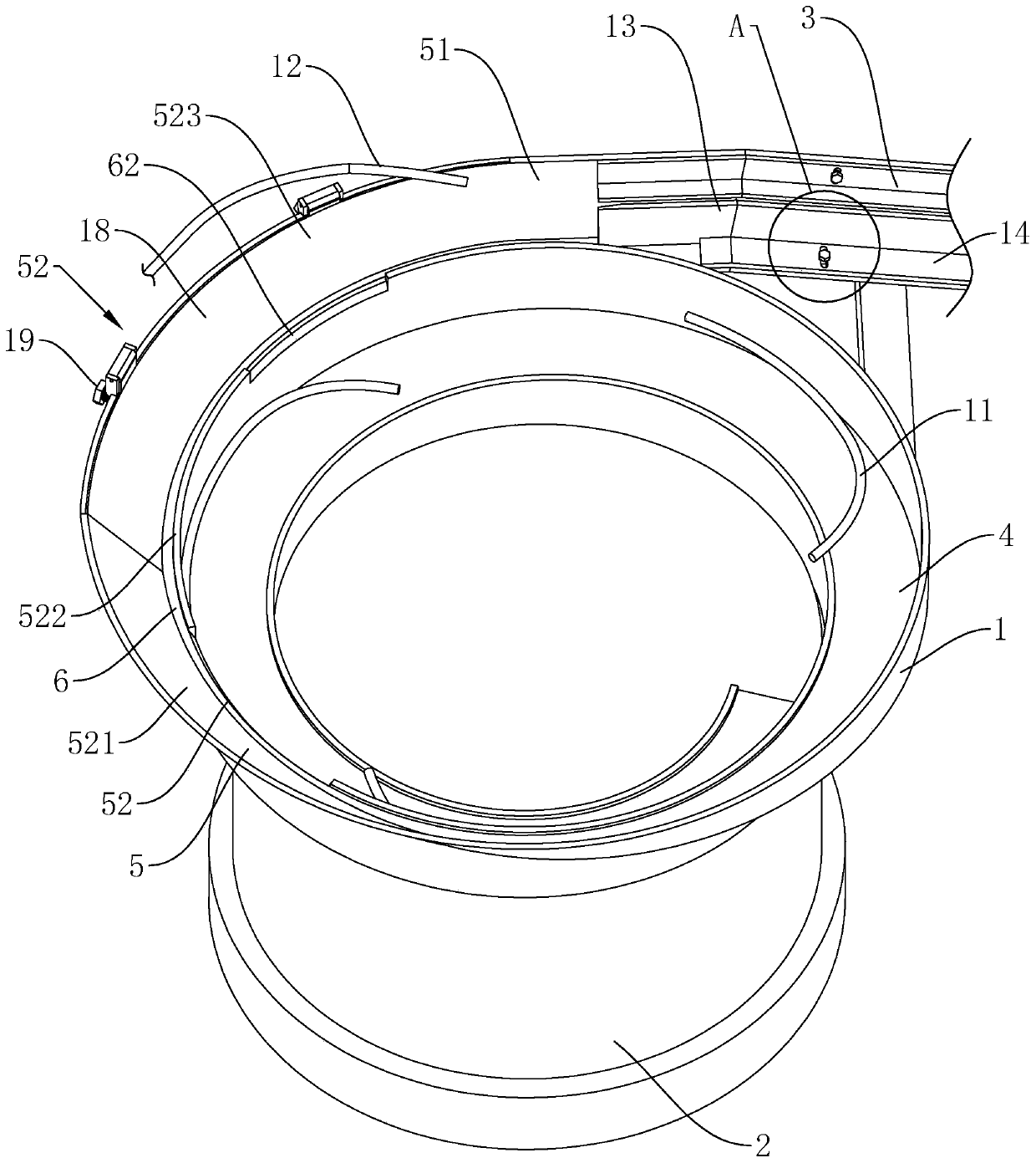
[0042] Embodiment 1: as image 3As shown, it is a thrust needle roller bearing cage feeding device disclosed in the present invention, which includes a storage bin 1 and a support frame 2 arranged up and down. The support frame 2 is provided with a controller (not shown in the figure) and a pulse electromagnetic Iron (not shown in the figure), the controller is electrically connected with the pulse electromagnet to control the vibration feeding of the storage bin 1. A screening channel is arranged in the storage bin 1, and the screening channel includes a first delivery channel 4 and a second delivery channel 5, and the second delivery channel 5 is located near the top of the storage bin 1 inner wall. , and the end of the second conveying channel 5 away from the first conveying channel 4 is an outlet 51 .

[0043] Such as image 3 As shown, the first conveying channel 4 is in a spiral shape and is arranged around the inner wall of the storage bin 1 from bottom to top, and th...

Embodiment 2

[0050] Embodiment 2: A kind of thrust needle roller bearing cage automatic needle loading machine, such as Figure 5 As shown, it includes a workbench 10, on which a needle roller feeding device 8 and a needle loading device 9 are arranged, and the needle roller feeding device 8 is connected to the needle loading device 9. The thrust needle roller bearing cage feeding device in Embodiment 1 is also provided on the workbench 10, and the thrust needle roller bearing cage feeding device is also connected with the needle loading device 9, and the cage can be automatically fed into the There are 9 needle loading devices.

[0051] Wherein the needle roller feeding device 8, the needle loading device 9 and the specific needle loading process are all disclosed by the patent No. CN203516486U, and will not be repeated here.


PUM


Abstract

The invention discloses a thrust needle roller bearing cage feeding device and an automatic needle-assembling machine and belongs to the field of needle roller bearing assembling equipment. The thrustneedle roller bearing cage feeding device comprises a storage hopper for vibrating feeding. A first conveying channel is formed in the inner wall of the storage hopper. A spirally-arranged second conveying channel is formed on the inner wall position close to the top of the storage hopper. The second conveying channel is obliquely arranged. The dip angle of the second conveying channel presents agradual-increasing trend along the direction away from the first conveying channel. A discharging port is formed in the end, away from the first conveying channel, of the second conveying channel. Ascreening segment is formed in the position, close to the discharging port, in the second conveying channel. A resistant strip is arranged on the side, facing the center of the storage hopper, of thescreening segment in an extending manner. A final screening notch is formed in a position, close to the discharging port, in the resistant strip. A cage which is attached to the screening segment fromthe front side falls into the storage hopper when passing the final screening notch. According to the thrust needle roller bearing cage feeding device, the function of positive and negative recognition of the cage in the automatic feeding process can be achieved, and thus the effect of improving efficiency is achieved.

Description

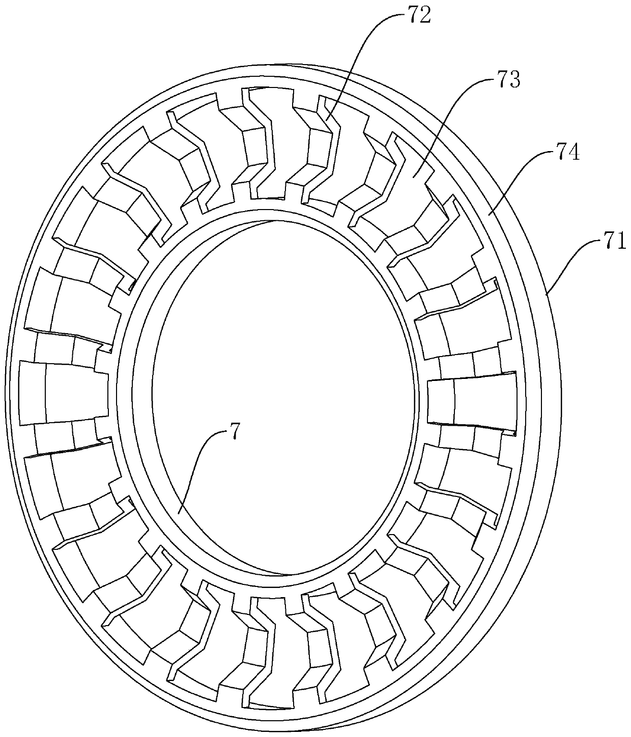
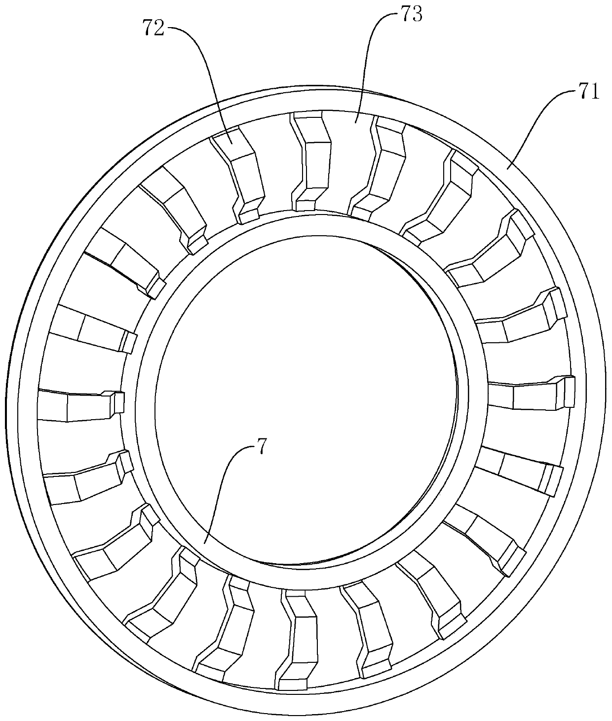
technical field [0001] The invention relates to the technical field of needle roller bearing assembly equipment, in particular to a thrust needle roller bearing retainer feeding device and an automatic needle loading machine. Background technique [0002] Thrust needle roller bearings are mainly used to bear axial and radial combined loads mainly under axial loads. This kind of bearings has a low friction factor, low speed, and self-aligning performance. Among them, the needle roller and the cage are the main components of the thrust bearing. Generally, there are a large number of needle rollers, which can withstand high thrust loads. [0003] As attached to the manual figure 1 and 2 As shown, the cage in the prior art includes an inner ring 7 and an outer ring 71 coaxially arranged, and a connecting strip 72 is fixedly arranged between the inner ring 7 and the outer ring 71, and between adjacent connecting strips 72 A window hole 73 for fitting the needle roller is forme...

Claims


Application Information

Patent Timeline
Patent Type & Authority Applications(China)
IPC IPC(8): F16C43/06
CPCF16C43/06
Inventor 陆兴培秦丹丹
Owner SUZHOU JINCHENG BEARING
Learn More