
Detection device for detonating signal of perforating magnetoelectric detonator

A detonation signal and detection device technology, applied in fuzes, weapon accessories, offensive equipment, etc., can solve the problems of unfavorable on-site operation, lack of oscilloscope, high cost, etc., and achieve the effect of avoiding engineering accidents and low power consumption

Pending Publication Date: 2019-08-27
XINJIANG INST OF ENG
View PDF0 Cites 0 Cited by
  • Summary
  • Abstract
  • Description
  • Claims
  • Application Information

AI Technical Summary

Problems solved by technology

The oscilloscope can be used to observe the waveform curves of various signal amplitudes changing with time, and it can also be used to test various electric quantities, such as voltage, current, frequency, phase difference, amplitude modulation, etc., which has the following disadvantages: high cost; Unintuitive, the oscilloscope has no intuitive frequency, only images can be obtained, and manual calculation is required, which is not conducive to on-site operation; the operation is difficult, because the two test leads need to be connected to the magnetic positioning interface, and both hands are required to operate at the same time, and the oscilloscope can no longer be used at this time To operate; the technical difficulty is relatively high. Since the detonation signal is a signal with a duration of only a few milliseconds, it is time-consuming and laborious to use an oscilloscope to capture the detonation signal. Unskilled operation may also lead to no effective signal. Ordinary ground workers generally cannot complete it. It needs to be operated by engineers with certain technical strength

Method used


Image

  • Detection device for detonating signal of perforating magnetoelectric detonator
  • Detection device for detonating signal of perforating magnetoelectric detonator
  • Detection device for detonating signal of perforating magnetoelectric detonator

Examples


Embodiment

[0029] The frequency detector is mainly used to detect the detonation signal given by the magnetoelectric detonator detonator. The signal is a signal with a short pulse (about 0.1 second) and a high frequency (tens or even hundreds of KHz). If it cannot be used before construction Testing the signal cannot guarantee that the construction can be carried out normally and smoothly or even cause an engineering accident. Therefore, it is necessary to measure this detonation signal. The invention provides a perforation magnetoelectric detonator detonation signal detection device which can intuitively detect whether the detonation signal can be accurately transmitted to the detonator for the purpose of avoiding engineering accidents.

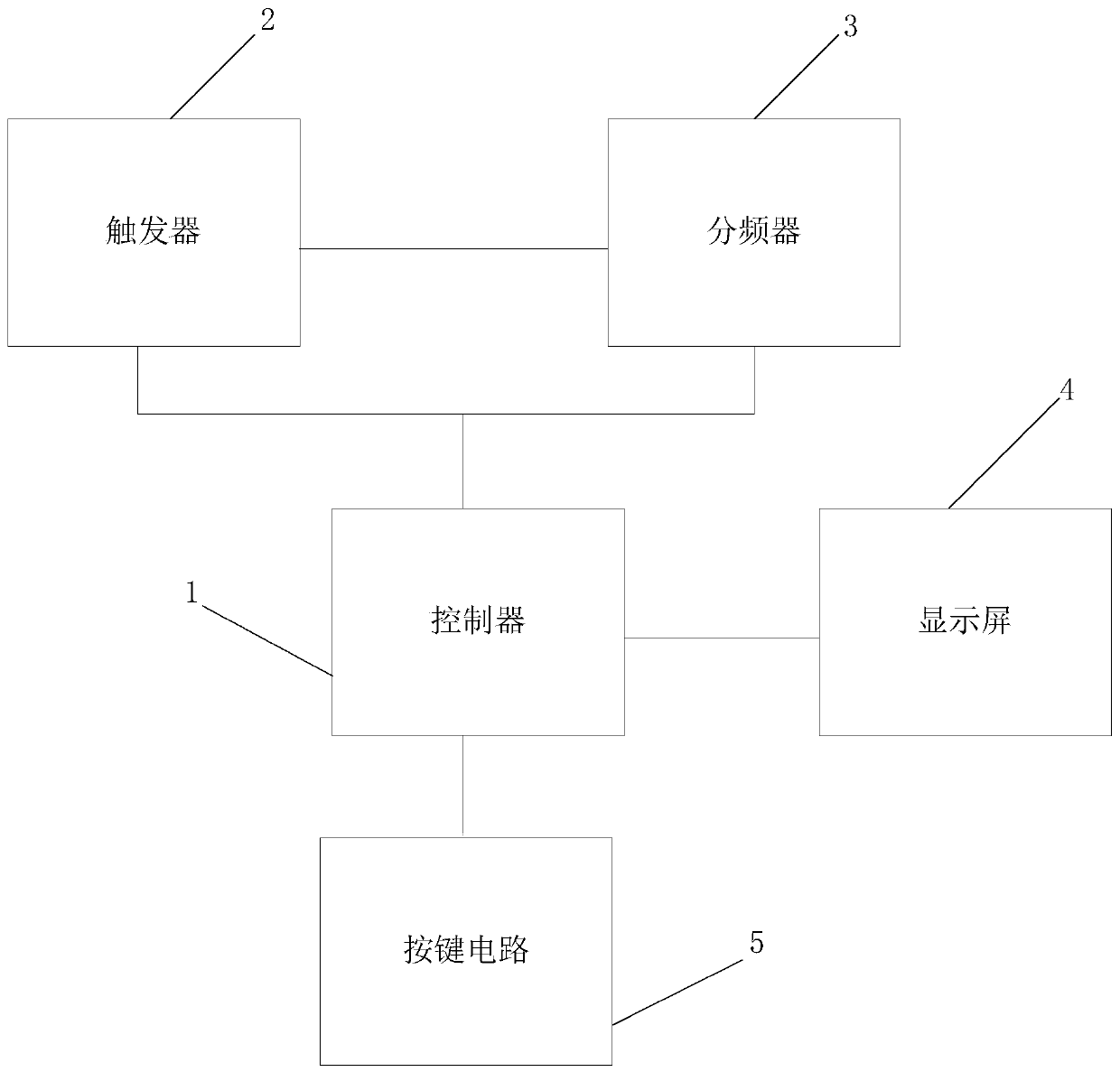
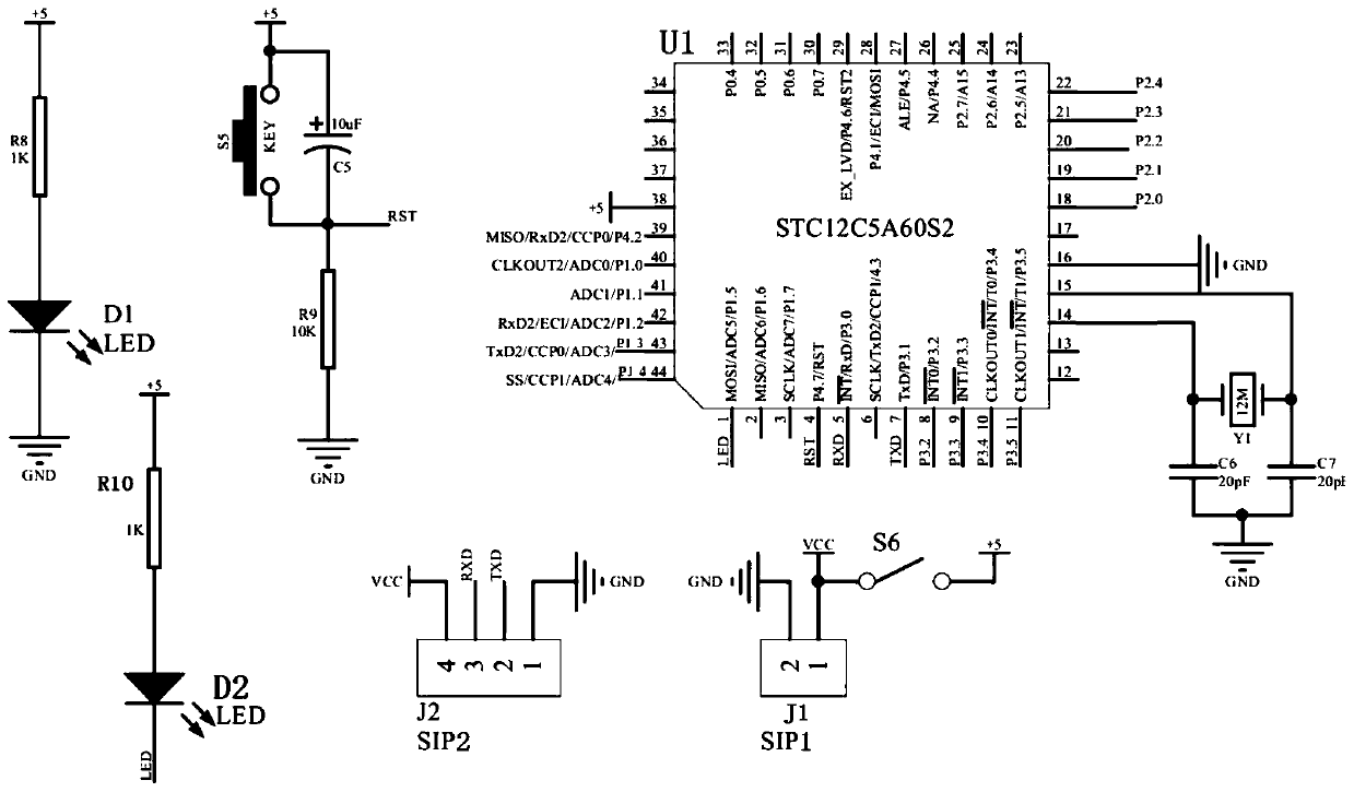
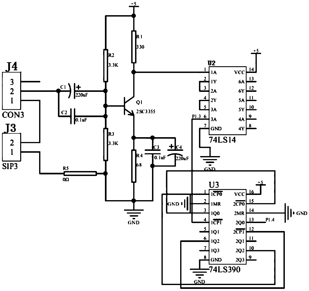
[0030] Such as figure 1 As shown, the present invention discloses a perforating magnetoelectric detonator detonation signal detection device, including a controller 1, and a trigger 2, a frequency divider 3, a display screen 4, and a button connected to th...


PUM


Abstract

The invention provides a detection device for a detonating signal of a perforating magnetoelectric detonator; the detection device comprises a controller as well as a trigger, a frequency divider, a display screen and a key circuit which are respectively connected with the controller, wherein the trigger is connected with the frequency divider. Through the above design, the detection device provided by the invention can measure the frequency of an electrical signal, especially the detonating signal, and set a specific frequency, so the signal of the frequency can be detected; and when the frequency is detected, an indicator light is illuminated to display the signal visually; and judging that the detonator and the connected perforator are in a normal working state, and the electric signalof the detonator can be normally provided to a detonator foot line to complete the normal construction; and the occurrence of engineering accidents can be avoided. The detection device for the detonating signal of the perforating magnetoelectric detonator provided by the invention has the advantages of simple structure, reasonable design, low cost and strong popularization and application value.

Description

Technical field [0001] The invention belongs to the technical field of magnetron detonation signal detection, and in particular relates to a device for detecting the detonation signal of a magnetron detonator for perforation. Background technique [0002] In the petroleum industry, it is basically necessary to use perforating operations on specific well sections, that is, to install perforating bullets in the perforating gun and connect with the magnetic positioning. After the magnetic positioner completes the depth calibration in the well, the detonator on the surface generates the detonation signal. , Through the cable and magnetic locator to reach the detonator in the perforating gun and explode the detonating index to detonate the perforating bullet, so that the metal jet contained in the perforating bullet penetrates the casing and penetrates part of the formation so that the oil and gas can flow into the well. The process of later mining. After the depth calibration of the...

Claims


Application Information

Patent Timeline
IPC IPC(8): F42C21/00
CPCF42C21/00
Inventor 齐兴华谢啸虎韩乐善崔江波景献明向旻安然李玲
Owner XINJIANG INST OF ENG
Learn More