Optical fiber collimation system with adjustable rotation angle

A technology of optical fiber collimation and angle rotation, which is applied in optics, optical components, instruments, etc., can solve problems that cannot meet various needs and limit the application of collimation systems, and achieve the effect of simple and practical structure, convenient adjustment, and reduced lateral size

Active Publication Date: 2019-08-27
UNION OPTIC
View PDF11 Cites 8 Cited by
  • Summary
  • Abstract
  • Description
  • Claims
  • Application Information

AI Technical Summary

Problems solved by technology

Due to the optical energy concentration, directivity and good monochromaticity of fiber laser, the application of fiber laser in all walks of life is more and more common. In industrial production and scientific research, people hope that the collimated light of fiber laser The energy and polarization state are adjustable, and the mechanical structure can be more compact. At present, the existing fiber laser collimator structures on the market are mostly straight collimation systems. The optical lenses in the system include common single lenses with different focal powers. It cannot meet people's diverse needs for different polarization states and energy levels of the outgoing light. At the same time, the total length of the system caused by the straight tube design also greatly limits the application of the collimation system in industrial production and scientific research.

Method used


Image

  • Optical fiber collimation system with adjustable rotation angle
  • Optical fiber collimation system with adjustable rotation angle
  • Optical fiber collimation system with adjustable rotation angle

Examples


Embodiment Construction

[0022] The technical solutions of the present invention will be clearly and completely described below in conjunction with the accompanying drawings in the present invention. Obviously, the described embodiments are only a part of the embodiments of the present invention, not all of them. Based on the embodiments of the present invention, all other embodiments obtained by persons of ordinary skill in the art without making creative efforts belong to the protection scope of the present invention.

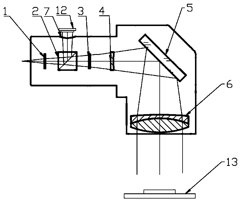
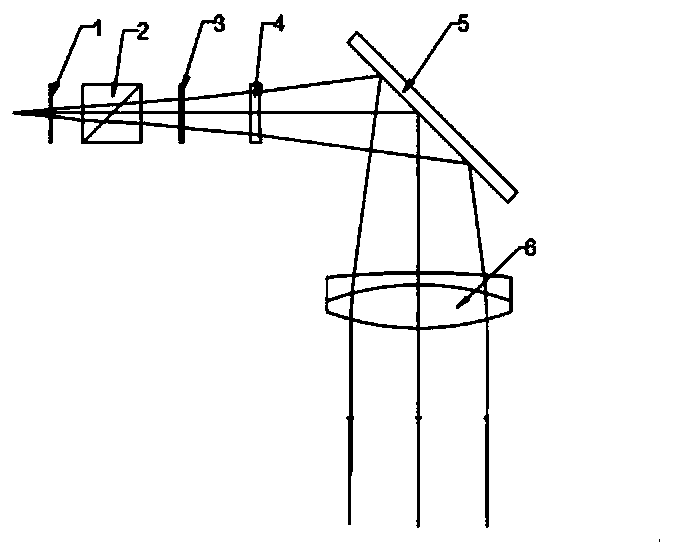
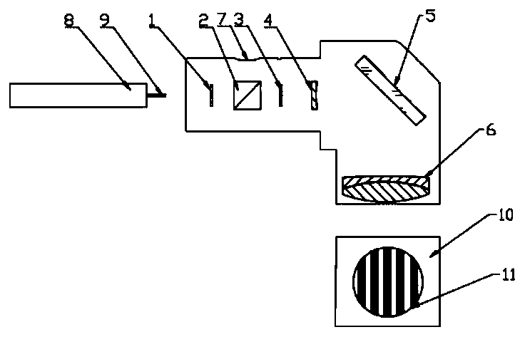
[0023] Please refer to the attached Figures 1 to 2 , an optical fiber collimation system with adjustable rotation angle, the laser light source connected to the optical fiber emits the collimated light after passing through the optical fiber collimation system, and the optical fiber collimation system includes a lens barrel and sequentially arranged in the lens barrel 1 / 2 wave plate, polarization beam splitter, 1 / 4 wave plate, plano-concave lens, mirror and doublet lens, the 1 / 2 wav...


PUM


Abstract

The invention discloses an optical fiber collimation system with an adjustable rotation angle. Laser emitted when a laser light source is connected with an optical fiber passes through an optical fiber collimation system to emit collimation light. The optical fiber collimation system comprises a lens cone, a 1/2 wave plate, a polarization splitting prism, a 1/4 wave plate, a planoconcave lens, a reflecting mirror and a double-gluing optical lens, wherein the 1/2 wave plate, the polarization splitting prism, the 1/4 wave plate, the planoconcave lens, the reflecting mirror and the double-gluingoptical lens are arranged in the lens cone in sequence; the 1/2 wave plate is used for rotating to change the polarization state of incident light; the polarization splitting prism is used for changing the energy of the emergent light; the 1/4 wave plate is used for rotating to change the polarization state of emergent light; and after emergent light, which passes through the 1/2 wave plate, the polarization splitting prism and the 1/4 wave plate, is subjected to beam expanding through the planoconcave lens, the emergent light is emitted to the double-gluing optical lens through the reflectingmirror and is then collimated through the double-gluing optical lens. The invention also discloses a wavefront debugging method for the optical fiber collimation system with the adjustable rotation angle.

Description

technical field [0001] The invention relates to the technical field of optical equipment, in particular to an optical fiber collimation system with high collimation, compact structure, excellent beam quality, and adjustable output spot energy and polarization state and a debugging method thereof, specifically an optical fiber with adjustable rotation angle collimation system. Background technique [0002] With the rapid development of laser and optical fiber-related technologies, laser-related products are becoming more and more mature, and the degree of commercialization continues to increase. Due to the optical energy concentration, directivity and good monochromaticity of fiber laser, the application of fiber laser in all walks of life is more and more common. In industrial production and scientific research, people hope that the collimated light of fiber laser The energy and polarization state are adjustable, and the mechanical structure can be more compact. At present,...

Claims


Application Information

Patent Timeline
Patent Type & Authority Applications(China)
IPC IPC(8): G02B27/30G02B27/28G02B27/62
CPCG02B27/30G02B27/286G02B27/62
Inventor 贺鹏吴警政李学雷
Owner UNION OPTIC
Why Eureka
Try Eureka