Supercharge Your Innovation With Domain-Expert AI Agents!

Self-fixing manual cutting device for processing building steel bars

A technology for building steel bars and cutting devices, which is applied in cleaning methods and utensils, cleaning methods using gas flow, chemical instruments and methods, etc. The effect of improving cutting quality, high reliability and strong practicability

Inactive Publication Date: 2019-08-30
林婷瑜
View PDF8 Cites 3 Cited by
  • Summary
  • Abstract
  • Description
  • Claims
  • Application Information

AI Technical Summary

Problems solved by technology

[0003] At present, most of the domestic buildings are built with steel bars, and the concrete is poured into shape. Steel bars are indispensable in building materials. When steel bars are used, the steel bars will be cut to reach a suitable length for easy use. The cutting machine can not be used in the work of cutting steel bars in the prior art. When it is fixed, the steel bar will deviate during cutting, and the cutting accuracy is not high, which affects the efficiency. Generally, the staff cuts manually. After a long working time, people will feel tired, which will affect the cutting accuracy. During the cutting work, a lot of sparks or dust are generated, accompanied by high temperature, which will cause great damage to the cutter and reduce the service life of the cutter
[0004] Chinese patent (notification number: CN208542879U) discloses a high-efficiency building steel bar cutting machine, including a floor mechanism, a lifting mechanism, a cutting mechanism, and a cooling mechanism. Cutting mechanism, one side of the bottom plate mechanism is provided with a cooling mechanism, the bottom plate mechanism includes a bottom plate, a steel bar guide groove, a pressing sheet, a partition, a rubber leather pad, and an adjusting screw, and the bottom plate is a square structure and one side is provided with a steel bar guide The two ends of the steel bar guide groove are respectively provided with pressing sheets. Although the device can realize automatic cutting of steel bars to a certain extent, it needs forward and reverse servo motors for each cutting, which not only increases the operation steps, but also Increased cost, therefore, requires further improvement

Method used


Image

  • Self-fixing manual cutting device for processing building steel bars
  • Self-fixing manual cutting device for processing building steel bars
  • Self-fixing manual cutting device for processing building steel bars

Examples


Embodiment 1

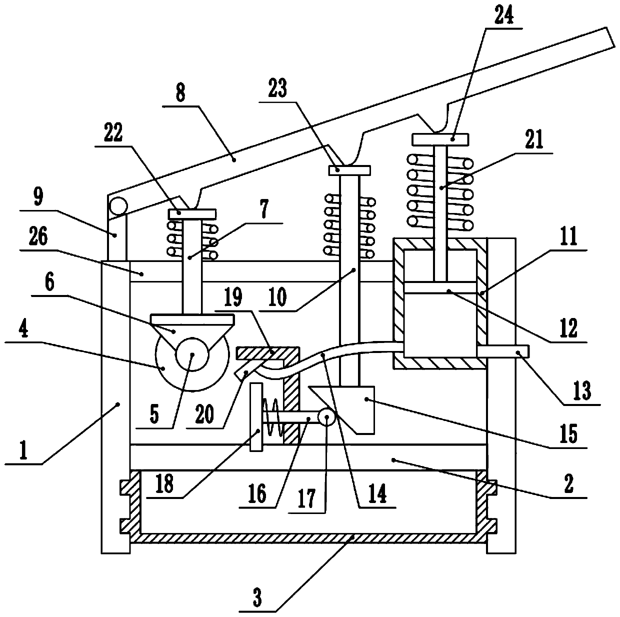
[0028] refer to Figure 1~3 , in an embodiment of the present invention, a self-fixing manual cutting device for processing steel bars for construction, comprising a support frame 1, a workbench 2 is installed in the middle of the lower end of the support frame 1, and a slag storage box 3 is installed at the bottom of the workbench 2, It is used to collect waste slag generated during the cutting process. The two ends of the slag storage box 3 are slidably connected to the bottom end of the support frame 1. A fixing plate 26 is installed on the top of the support frame 1. A cutting column 7 is installed in the middle of the left side of the fixing plate 26. The lower end of the cutting column 7 is equipped with a motor base 6, and the lower end of the motor base 6 is equipped with a cutting motor 5, which is used to drive the cutting wheel 4 to cut and realize the cutting effect. The output end of the cutting motor 5 is equipped with a cutting wheel 4, and the fixed plate 26 Th...

Embodiment 2

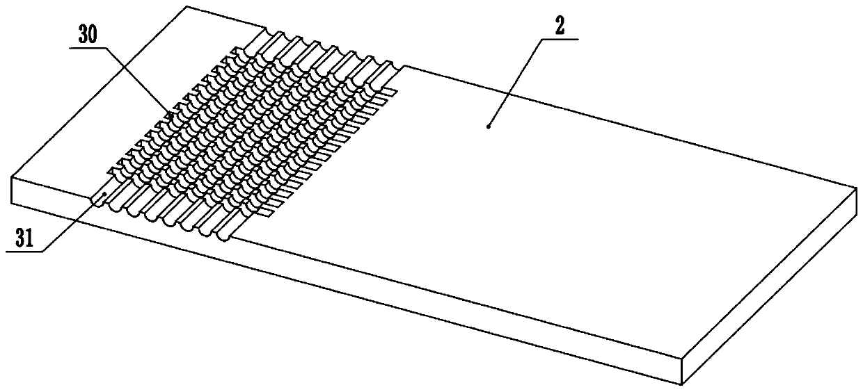
[0030] In another embodiment of the present invention, the difference between this embodiment and the above-mentioned embodiment is that several cutting grooves 30 are provided on the left side of the workbench 2, so that the cutting wheel 4 can give way during the cutting process. , the vertical position of the cutting groove 30 is equipped with a reinforcement groove 31, which is used for placing the reinforcement to be cut.

[0031]In the present invention, when working, the steel bar is placed on the steel bar groove 31 on the workbench 2, and then the cutting motor is started. During the cutting of steel bars, at the same time, the lifting shaft 7 moves downward, and the guide column 16 drives the clamping block 18 to move towards the steel bar through the action of the lifting block 15, so as to realize the extrusion and fixing of the steel bars, and at the same time, the exhaust plate 12 moves along the row The air box 11 moves downwards, and the gas is sprayed out thro...


PUM


Abstract

The invention discloses a self-fixing manual cutting device for processing building steel bars, and relates to the cutting device for the building steel bars. The device comprises a support frame, wherein a workbench is installed in the middle of the lower end of the support frame; a fixing plate is installed at the top end of the support frame; a cutting column is installed in the middle of the left side of the fixing plate; a motor seat is installed at the lower end of the cutting column; a cutting motor is installed at the lower end of the motor seat; cutting wheels are installed at the output end of the cutting motor; a lifting shaft is installed in the middle of the fixing plate; a lifting block is installed at the bottom end of the lifting shaft; a guide ball is contacted to the leftside of the lifting block; a guide column is connected to the left side of the guide ball; a clamping block is connected to the left side of the guide column through a guide frame arranged in the middle of the upper end of the workbench; and an exhaust box is installed in the middle of the right side of the fixing plate. With the device, the self-fixing type cutting of the building steel bars isrealized, and meanwhile, the waste residues generated in the cutting process can be timely cleaned through the matching between the exhaust box and an air nozzle, so that the cutting quality is further improved.

Description

technical field [0001] The invention relates to a cutting device for building steel bars, in particular to a self-fixing manual cutting device for processing building steel bars. Background technique [0002] Building steel bars refer to various steel bars, steel wires, etc. used in reinforced concrete. Building steel bars refer to various steel bars, steel wires, etc. used in reinforced concrete. Steel bars are divided into: non-alloy steel bars, low-alloy steel bars, and alloy steel bars according to steel types. Steel bars are divided into hot-rolled bars, heat-treated bars, waste heat-treated bars, cold-rolled bars, and cold-drawn bars according to production processes. According to the shape, the steel bars are divided into: smooth round steel bars and deformed steel bars, and the deformed steel bars are crescent rib steel bars (spiral, herringbone, with longitudinal ribs, without longitudinal ribs). [0003] At present, most of the domestic buildings are built with s...

Claims


Application Information

Patent Timeline
Patent Type & Authority Applications(China)
IPC IPC(8): B21F11/00B08B5/02
CPCB08B5/02B21F11/00
Inventor 林婷瑜
Owner 林婷瑜
Features
  • R&D
  • Intellectual Property
  • Life Sciences
  • Materials
  • Tech Scout
  • Unparalleled Data Quality
  • Higher Quality Content
  • 60% Fewer Hallucinations
Learn More