
Free-form optical component surface shape error on-machine detecting device and method based on white light confocal theory

A technology of white light confocal and optical components, which is applied in the direction of using optical devices, measuring devices, measuring/indicating equipment, etc., can solve the problems of poor efficiency, easy damage to the surface of optical components by probes, and low precision, so as to save time and improve Ultra-precision machining efficiency and the effect of improving detection accuracy

Active Publication Date: 2019-08-30
HARBIN INST OF TECH
View PDF7 Cites 7 Cited by
  • Summary
  • Abstract
  • Description
  • Claims
  • Application Information

AI Technical Summary

Problems solved by technology

[0006] The purpose of the present invention is to solve the problems of low precision and poor efficiency caused by the off-line detection method of the existing free-form surface optical element surface error detection device, and the problem that the probe contact detection is easy to damage the surface of the optical element. On-machine detection device and method for surface error of free-form surface optical element based on focal principle

Method used


Image

  • Free-form optical component surface shape error on-machine detecting device and method based on white light confocal theory
  • Free-form optical component surface shape error on-machine detecting device and method based on white light confocal theory
  • Free-form optical component surface shape error on-machine detecting device and method based on white light confocal theory

Examples


specific Embodiment approach 1

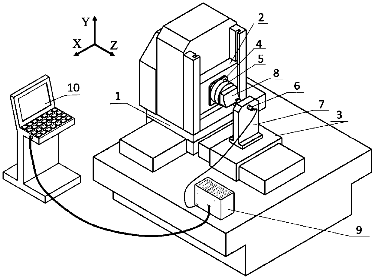
[0046] Specific implementation mode one: the following combination figure 1 Describe this embodiment, the free-form surface optical element surface shape error detection device based on the principle of white light confocal in this embodiment, the detection device includes X-axis moving stage 1, Y-axis moving stage 2, Z-axis moving stage 3, Rotary shaft 4, vacuum chuck 5, white light confocal probe 6, fixture 7, controller 9 and machine tool industrial computer 10;

[0047] The X-axis and the Z-axis are two axes on the horizontal plane, and the Y-axis is the longitudinal axis perpendicular to the horizontal plane. The rotation axis 4 is installed on the Y-axis moving table 2, and a vacuum chuck 5 is installed on the rotation axis 4. The component 8 is installed on the vacuum chuck 5, the white light confocal measuring head 6 is installed on the Z-axis moving table 3 through the fixture 7, the outgoing light of the white light confocal measuring head 6 is parallel to the Z-axis...

specific Embodiment approach 2

[0048] Embodiment 2: In this embodiment, Embodiment 1 is further described. The measuring range of the white-light confocal probe 6 is -75-75 μm, and the inclination range of the surface of the free optical element that can be measured is ±42°.

specific Embodiment approach 3

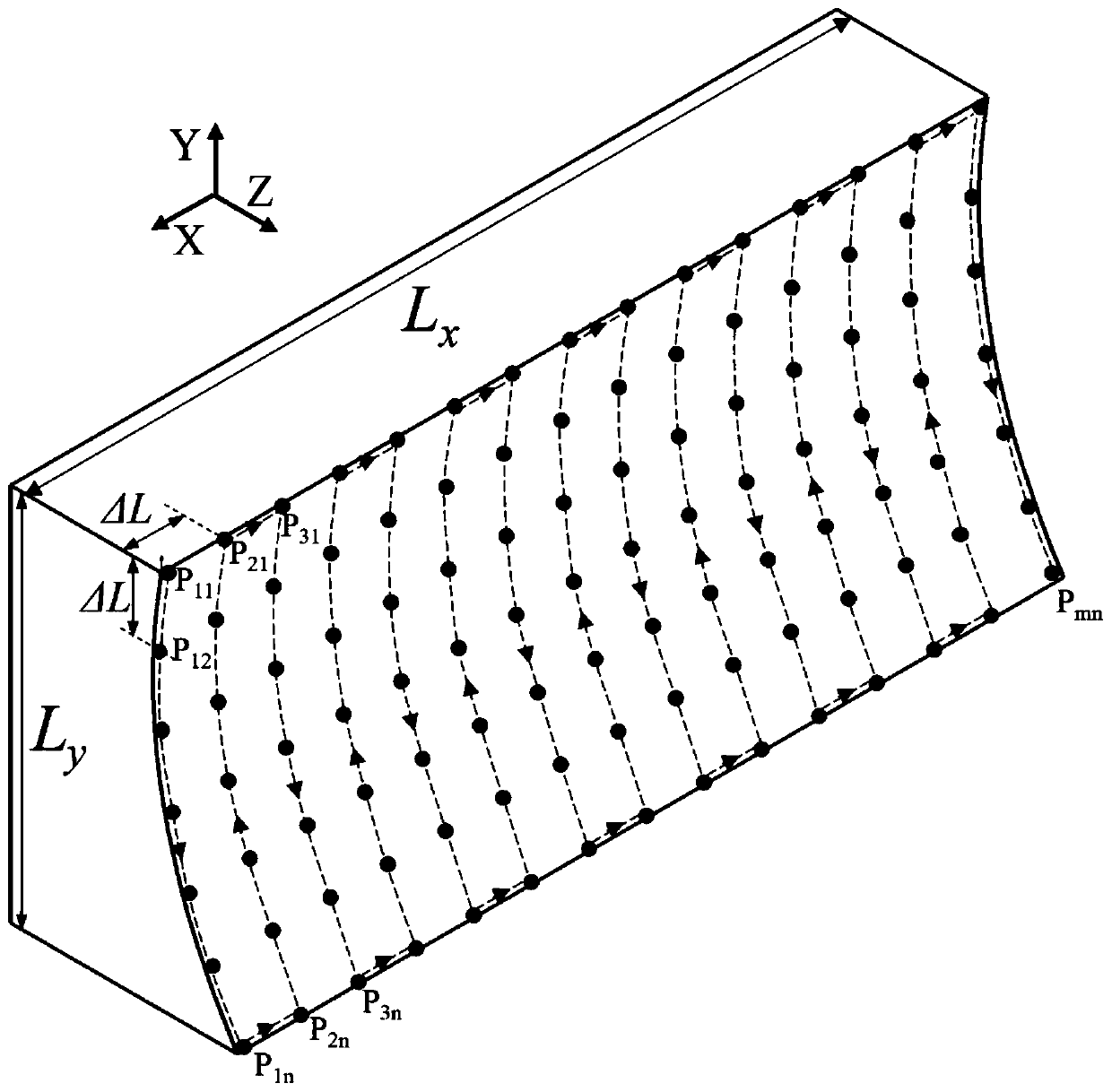
[0049] Specific implementation mode three: the following combination figure 2 Describe this embodiment, the on-machine detection method for the surface error of free-form surface optical elements based on the principle of white light confocal described in this embodiment, the specific process of the detection method is:

[0050] S1. Adjust the X-axis moving stage 1 and the Y-axis moving stage 2, so that the white light confocal probe 6 is facing the point on the upper left edge of the free-form surface optical element 8 to be measured, and adjust the white light confocal measuring head 6 through the Z-axis moving stage 3 The distance from the free-form surface optical element 8 to be measured is such that the output detection data of the white light confocal probe 6 is 0;

[0051] S2. According to the free-form surface description equation, generate a three-dimensional coordinate point sequence with equal intervals between the X coordinate and the Y coordinate, insert the gen...


PUM


Abstract

The invention discloses a free-form optical component surface shape error on-machine detecting device and method based on a white light confocal theory, and belongs to the technical field of ultra-precision machining of free-form optical components. The problem that an existing free-form optical component surface shape error detecting devices adopts an offline detecting manner, and consequently the precision is low, and the efficiency is poor is solved. According to the free-form optical component surface shape error on-machine detecting device based on a white light confocal theory, a shaft Xand a shaft Y are two shafts on the horizontal plane, the shaft Y is a longitudinal shaft perpendicular to the horizontal plane, and a rotary shaft is mounted on a Y-shaft moving table, and a vacuumsuction cup is mounted on the rotary shaft. A free-form optical component to be detected is mounted on the vacuum suction cup, a white light confocal detecting head is mounted on a Z-shaft moving table through a clamp, and the emitted light of the white light confocal detecting head is parallel to the Z-shaft moving table. The emitted light penetrates through the center line of the rotary shaft, and detecting data of the white light confocal detecting head is transmitted to a machine tool industrial personal computer through a controller. The free-form optical component surface shape error on-machine detecting device and method are used for detecting the free-form optical component.

Description

technical field [0001] The invention relates to an on-machine detection device and a detection method for the surface error of a free-form optical element, and belongs to the technical field of ultra-precision processing of the free-form optical element. Background technique [0002] Free surface optical elements have no constant axis of rotation, and their shapes are arbitrary, regular or irregular. As the next generation of modern optical elements, they have the advantages of excellent optical performance and good system integration. They are used in aviation, deep diving, green energy and precision It has great application potential in optical systems such as lighting. The development of free-form optical components provides greater design flexibility and innovation scope for optical design, but at the same time poses new challenges to optical manufacturing and inspection. [0003] Although the machining of free-form optical components can be realized by multi-axis linka...

Claims


Application Information

Patent Timeline
Patent Type & Authority Applications(China)
IPC IPC(8): B23Q17/20G01B11/24
CPCB23Q17/20G01B11/24
Inventor 潘永成赵清亮郭兵王生吴小桥
Owner HARBIN INST OF TECH
Learn More