Test frame device for steel grits splashing trend for sand blasting machine equipment production

A technology of sandblasting machine and test stand, which is applied to used abrasive processing devices, metal processing equipment, grinding/polishing equipment, etc., can solve the waste of useless steel sand, cannot be tested by shot blasting machine, and cannot be pre-tested. and other problems, to achieve the effect of uniform quantity and reasonable structure of sandblaster

Active Publication Date: 2019-08-30
苏州因知成新能源有限公司
View PDF5 Cites 0 Cited by
  • Summary
  • Abstract
  • Description
  • Claims
  • Application Information

AI Technical Summary

Problems solved by technology

[0005] In order to solve the above-mentioned technical problems, the present invention provides a test frame device for the direction of steel grit splashing used in the production of sandblasting machine equipment, to solve the equipment discovery in the prior art, after the shot blasting machine or sandblasting machine equipment is produced, it cannot The shot blaster installed inside them is tested, and it is not possible to determine whether the steel grit sprayed by the shot blaster installed inside is evenly flying to the surrounding area. It cannot be pre-tested, so that when the steel grit is sprayed on the surface of the workpiece, it will cause useless steel grit. waste problem

Method used


Image

  • Test frame device for steel grits splashing trend for sand blasting machine equipment production
  • Test frame device for steel grits splashing trend for sand blasting machine equipment production
  • Test frame device for steel grits splashing trend for sand blasting machine equipment production

Examples


Embodiment

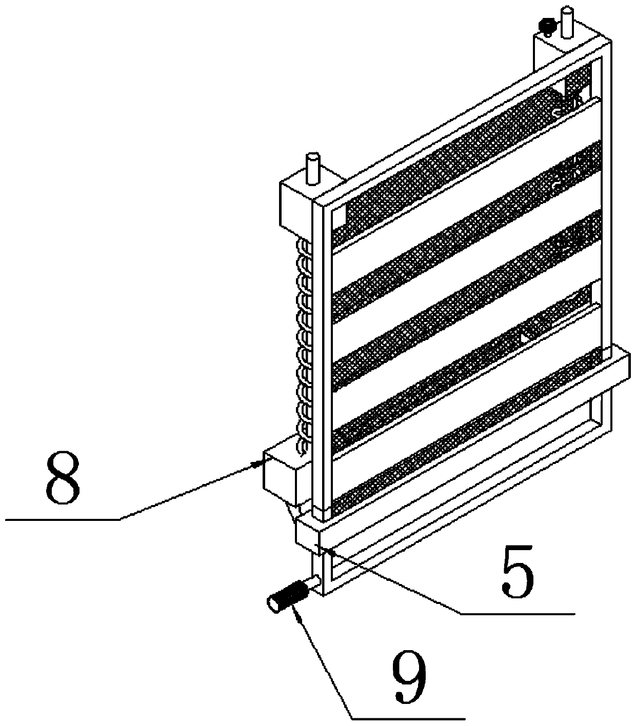
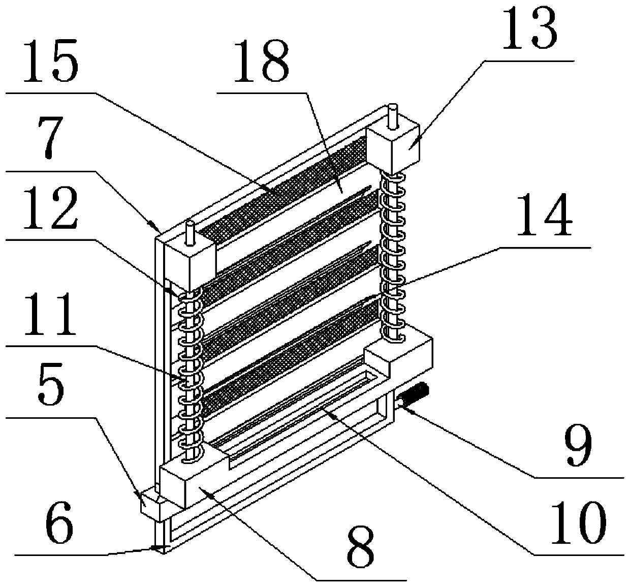
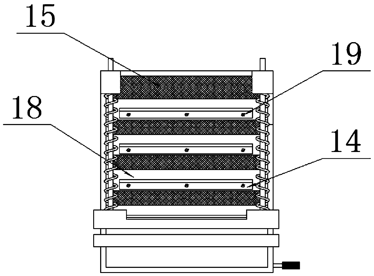
[0030] as attached figure 1 to attach Figure 8 Shown:

[0031] The invention provides a test frame device for the direction of steel grit splashing used in the production of sandblasting machine equipment, comprising: a sandblasting machine main body 1, a feed port 2, a top cover 3, a hinged door 4, a sliding seat 5, a stopper 6, and a frame 7. Mounting seat 8, lever 9, mounting groove 10, guide rod 11, return spring 12, guide pressure seat 13, sand board 14, observation net 15, lock post 16, lock hole 17, welding plate 18 and threaded plug 19; the top surface of the sliding seat 5 is near the inner position, and a mounting seat 8 is installed by tilting the outer edge; the two sides of the top surface of the mounting seat 8 are bonded and installed with a cylindrical rod structure in a vertical manner. guide rod 11, and a guide rod 11 is also sleeved on the outside of the guide rod 11; the frame 7 is a rectangular outer frame structure, and a guide press seat 13 is also in...


PUM


Abstract

The invention provides test frame device for steel grits splashing trend for sand blasting machine equipment production. The test frame device comprises a mounting base, a handle rod, a mounting groove, guide rods, a reset spring, a guide press base, a sand receiving plate, an observation mesh, a lock column, a lock hole, a welding plate and a threaded plug; a position, close to the inner position, of the top surface of a sliding base is provided with the mounting base through an inclined outer edge; the two sides of the top surface of the mounting base are provided with the guide rods with acylindrical rod structure in a vertical manner through bonding respectively, and the guide rod is arranged on the outer side of the guide rods in a sleeved mode; the frame is of a rectangular outer frame structure, the number of the steel grits flying to a certain position is determined, and if the number of the steel grits which are connected to the sand receiving plate at a certain position is large, it is proved that, and the installation angle of an impeller head on the sand blasting machine needs to be adjusted until the number of the steel grits sprayed on the sand receiving plates is more uniform. Therefore, the structure of the finally manufactured sand blasting machine is more reasonable, so that the steel grits thrown out by the impeller head installed in the sand blasting machine is more uniform in spattering.

Description

technical field [0001] The invention belongs to the technical field of sandblasting equipment manufacturing and production, and more specifically relates to a test frame device for the direction of steel sand splashing used in the production of sandblasting machine equipment. Background technique [0002] Due to the impact and cutting effect of abrasives on the surface of the workpiece, the surface of the workpiece can be obtained with a certain degree of cleanliness and different roughness, so that the mechanical properties of the surface of the workpiece are improved, thus improving the fatigue resistance of the workpiece and increasing its The adhesion between the coating and the coating prolongs the durability of the coating film, and is also conducive to the leveling and decoration of the coating. It removes impurities, variegated colors and oxide layers on the surface, and at the same time roughens the surface of the medium to eliminate the residual stress of the workpi...

Claims


Application Information

Patent Timeline
IPC IPC(8): B24C5/00B24C9/00
CPCB24C5/00B24C9/00
Inventor 戴圣洁
Owner 苏州因知成新能源有限公司
Why Eureka
Try Eureka