Multifunctional mechanical gripper

A multi-functional machine and claw technology, applied in the field of robotic hands, can solve the problems of time-consuming and labor-intensive, single practical function, and increase the cost of picking and placing, and achieve the effect of improving work efficiency, improving time-consuming and laborious, and increasing the scope of use.

Active Publication Date: 2019-08-30
JIANGSU UNIV
View PDF10 Cites 6 Cited by
  • Summary
  • Abstract
  • Description
  • Claims
  • Application Information

AI Technical Summary

Problems solved by technology

[0002] With the advancement of the machinery industry, the application of mechanical claws is becoming more and more extensive. Mechanical claws can be used in some difficult and harsh environments. It can pick and place objects of the same shape or roughly similar shapes, and its practical function is relatively single. In order to realize the pick and place of objects of different shapes or complex shapes, it is necessary to combine a variety of mechanical claws with different functions, which not only increases the cost of pick and place, time consuming

Method used


Image

  • Multifunctional mechanical gripper
  • Multifunctional mechanical gripper
  • Multifunctional mechanical gripper

Examples


Embodiment Construction

[0020] The present invention will be further described below in conjunction with the accompanying drawings and specific embodiments, but the protection scope of the present invention is not limited thereto.

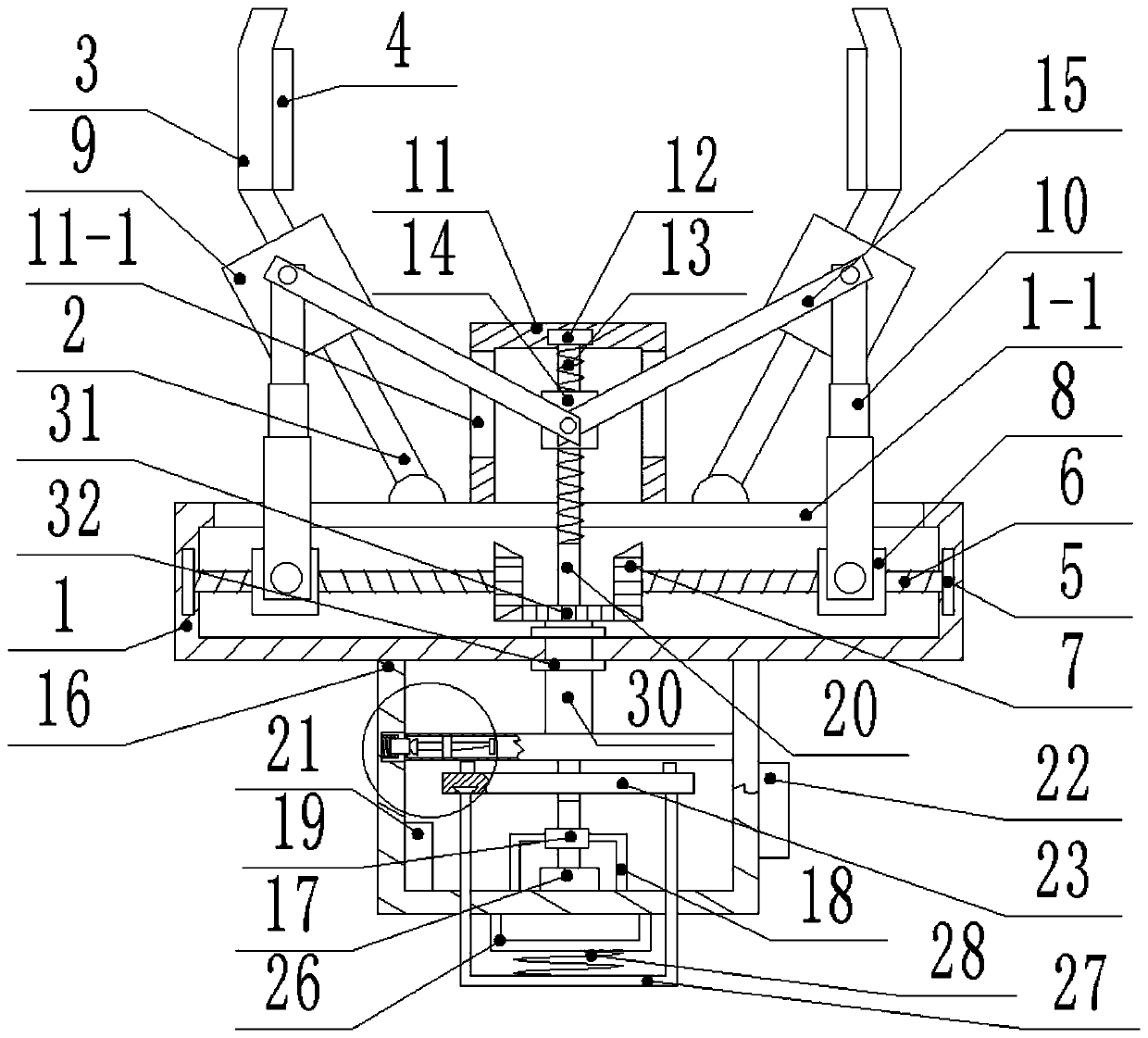
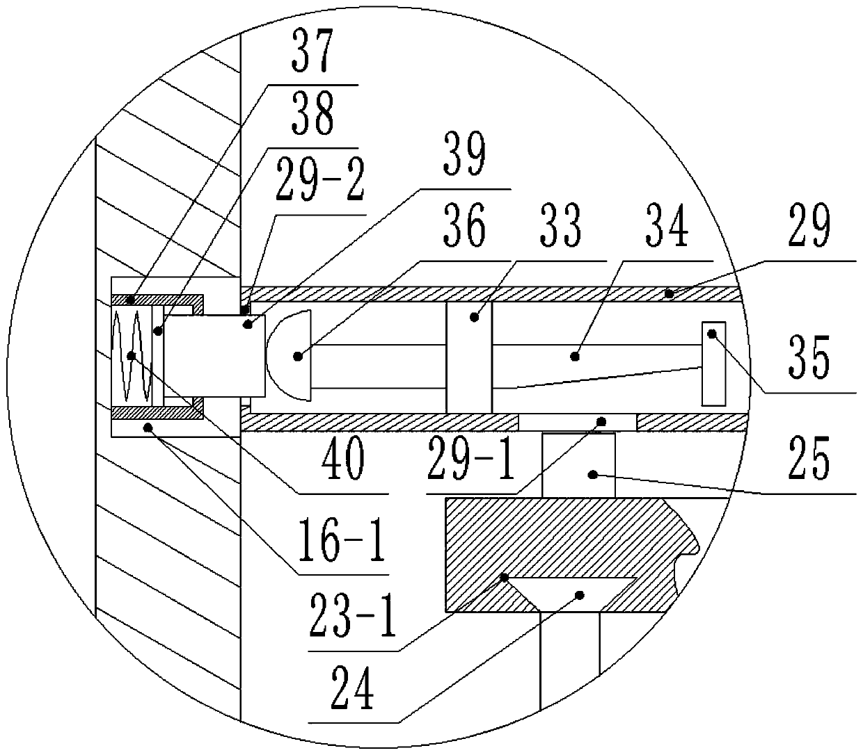
[0021] Such as figure 1 , figure 2 and image 3 As shown, the multifunctional mechanical claw of the present invention includes a clamping part, a transmission part, a traverse part and a clutch part;

[0022] The clamping part includes a first inclined bar 2, claws 3, a first box body 1, a first barrel body 11 and a second barrel body 16; at least two first barrel bodies are symmetrically hinged on the first box body 1. Slanting rods 2, the top of each first slanting rod 2 is fixedly connected with claws 3, and the side walls of the claws 3 are fixedly connected with frosted layers 4, the cross section of the first slanting rods 2 is square, and the first The first sliding block 9 is slidably connected to the inclined rod 2; the top surface of the first box body 1 is...


PUM


Abstract

The invention provides a multifunctional mechanical gripper. The multifunctional mechanical gripper comprises a clamping component and a driving component. The clamping component comprises first inclined rods, clamping jaws, a first box, a first barrel and a second barrel. At least two first inclined rods are symmetrically hinged to the first box. The top end of each first inclined rod is fixedlyconnected with one clamping jaw. A first sliding block is slidably connected to each first inclined rod. The top surface of the first box is fixedly connected with the first barrel. A second bearing is mounted on the inner top surface of the first barrel. The second bearing is used for supporting one end of a rotary shaft. A second threaded sleeve is connected to the rotary shaft through a screw thread pair. The rotary shaft rotates to drive the second threaded sleeve to do linear motion. The first sliding blocks are hinged to the second threaded sleeve through second inclined rods. The bottomsurface of the first box is fixedly connected with the second barrel. The driving component is fixed to the bottom of the second barrel. The other end of the rotary shaft penetrates through the firstbarrel and the second barrel to be connected with the driving component. The multifunctional mechanical gripper is simple in structure, diversified in function and high in practicality.

Description

technical field [0001] The invention relates to the technical field of robotic hands, in particular to a multifunctional mechanical gripper. Background technique [0002] With the advancement of the machinery industry, the application of mechanical claws is becoming more and more extensive. Mechanical claws can be used in some difficult and harsh environments. It can pick and place objects of the same shape or roughly similar shapes, and its practical function is relatively single. In order to realize the pick and place of objects of different shapes or complex shapes, it is necessary to combine a variety of mechanical claws with different functions, which not only increases the cost of pick and place, Also time consuming. Contents of the invention [0003] Aiming at the deficiencies in the prior art, the invention provides a multifunctional mechanical gripper with simple structure, various functions and strong practicability. [0004] The present invention achieves the ...

Claims


Application Information

Patent Timeline
IPC IPC(8): B25J15/02
CPCB25J15/0213
Inventor 张新星朱凯张国荣张腾
Owner JIANGSU UNIV
Why Eureka
Try Eureka