A kind of unmanned aerial vehicle image sensor control device and control method thereof

An image sensor and control device technology, which is applied to aircraft parts, transportation and packaging, etc., can solve the problems of increasing the swing range of camera shooting angles and the inability of drone cameras to shoot vertically upwards, so as to avoid shooting dead angles, ensure safety, and avoid The effect of occlusion

Active Publication Date: 2020-04-17
广东省岭南院勘察设计有限公司
View PDF1 Cites 0 Cited by
  • Summary
  • Abstract
  • Description
  • Claims
  • Application Information

AI Technical Summary

Problems solved by technology

[0004] The object of the present invention is to provide a UAV image sensor control device and its control method. In the present invention, the controller controls the first motor to drive the second connecting arm to swing, thereby controlling the extension range of the second connecting arm in the horizontal direction and the second connecting arm. The end of the three connecting arms is the moving area of ​​the camera. By controlling the second motor to drive the third connecting arm to swing, the angle of the camera can be directly controlled. The cooperation of the second connecting arm and the third connecting arm greatly increases the camera shooting In the swing range of the angle, the camera can make the lens go up or down vertically, avoiding the occlusion of the drone body when shooting upwards, and at the same time, it does not need to tilt the drone to shoot, so that the safety of the drone is guaranteed when it is working. The existing drone camera cannot shoot vertically upwards, and there is a technical problem of shooting dead angles;

Method used


Image

  • A kind of unmanned aerial vehicle image sensor control device and control method thereof
  • A kind of unmanned aerial vehicle image sensor control device and control method thereof
  • A kind of unmanned aerial vehicle image sensor control device and control method thereof

Examples


Embodiment Construction

[0038] The technical solutions of the present invention will be clearly and completely described below in conjunction with the embodiments. Apparently, the described embodiments are only some of the embodiments of the present invention, not all of them. Based on the embodiments of the present invention, all other embodiments obtained by persons of ordinary skill in the art without creative efforts fall within the protection scope of the present invention.

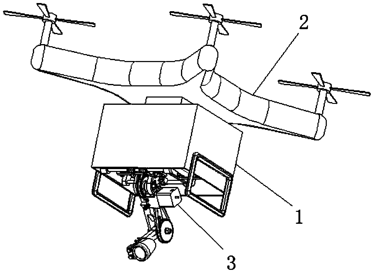
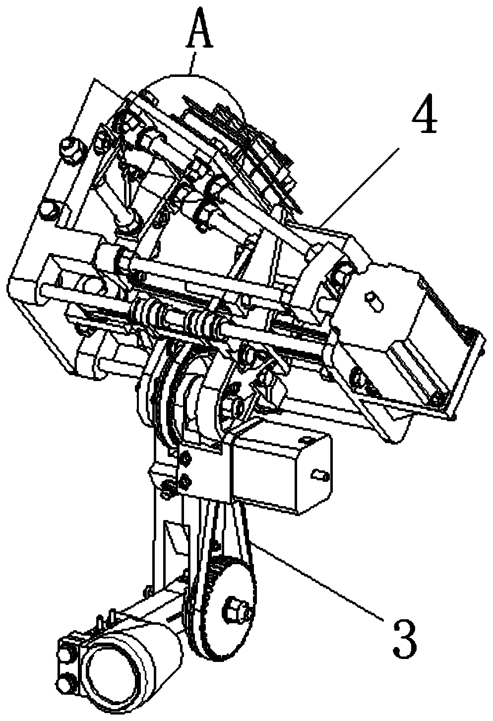
[0039] Such as Figure 1-9 As shown, a UAV image sensor control device includes a casing 1 and a UAV 2, the casing 1 is fixedly installed on the bottom of the UAV 2, and the inner side of the casing 1 is fixedly equipped with a moving mechanism 4. An angle adjustment mechanism 3 is connected to the bottom of the moving mechanism 4;

[0040] The moving mechanism 4 includes a connection seat 401, the outer surface of the connection seat 401 is fixedly connected with the inner wall of the housing 1, a support rod 402 is arran...


PUM


Abstract

The invention discloses an unmanned aerial vehicle image sensor control device and a control method thereof. The control device comprises a shell and an unmanned aerial vehicle, wherein the shell is fixedly installed at the bottom of the unmanned aerial vehicle, a moving mechanism is fixedly installed on the inner side of the shell, and the bottom of the moving mechanism is connected to an angle adjusting mechanism. According to the unmanned aerial vehicle image sensor control device and the control method thereof, a second connecting arm and a third connecting arm are matched, so that the swing range of a camera shooting angle is increased, and the shooting dead angle of the camera shooting by the unmanned aerial vehicle is avoided; the unmanned aerial vehicle is not required to tilt forshooting, so that the safety of the unmanned aerial vehicle during working is guaranteed; compared that the horizontal direction of the unmanned aerial vehicle is adjusted according to the horizontalflight of the unmanned aerial vehicle, the mobile camera can be adjusted more accurately through the moving angle adjusting mechanism in the control device; and movable clamping blocks are arranged tofix the angle adjusting mechanism, so that the movable clamping blocks are fixed with a guide sliding sleeve, the angle adjusting mechanism is more stable during moving, and therefore the shooting precision of the camera is guaranteed.

Description

technical field [0001] The invention relates to the technical field of unmanned aerial vehicle imaging, in particular to an unmanned aerial vehicle image sensor control device and a control method thereof. Background technique [0002] Unmanned aircraft, referred to as "unmanned aerial vehicle", is an unmanned aircraft controlled by radio remote control equipment and self-contained program control device, or is completely or intermittently operated autonomously by the on-board computer. Compared with manned aircraft, Drones tend to be better suited for those dangerous missions. According to the application field, UAV can be divided into military and civilian. In terms of military use, UAVs are divided into reconnaissance aircraft and target aircraft. In terms of civilian use, drones plus industry applications are the real rigid needs of drones; currently, they are used in aerial photography, agriculture, plant protection, miniature selfies, express delivery, disaster relie...

Claims


Application Information

Patent Timeline
Patent Type & Authority Patents(China)
IPC IPC(8): B64D47/08
CPCB64D47/08
Inventor 安贤泰邹璇
Owner 广东省岭南院勘察设计有限公司
Why Eureka
Try Eureka