Gas detecting and ventilating device and using method thereof

A ventilation device and gas detection technology, which is applied in the direction of sampling device, pump test, liquid variable capacity machinery, etc., can solve the problems of low ventilation efficiency, poor accuracy, low efficiency of real-time gas detection, etc., and improve the contact efficiency , low noise, and the effect of improving the active response ability

Inactive Publication Date: 2019-08-30
TSINGHUA UNIV
View PDF5 Cites 2 Cited by
  • Summary
  • Abstract
  • Description
  • Claims
  • Application Information

AI Technical Summary

Problems solved by technology

[0005] The purpose of the present invention is to provide a gas detection and ventilation device and its use method to solve the problems of low efficiency, poor accuracy and low ventilation efficiency in real-time gas detection in the prior art

Method used


Image

  • Gas detecting and ventilating device and using method thereof
  • Gas detecting and ventilating device and using method thereof
  • Gas detecting and ventilating device and using method thereof

Examples


Embodiment 1

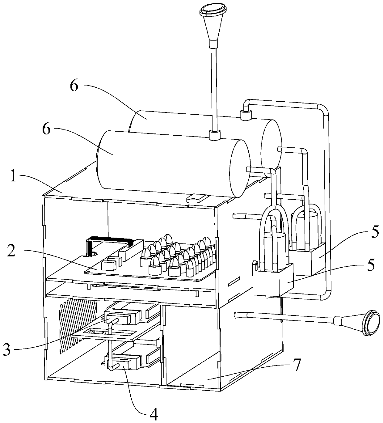
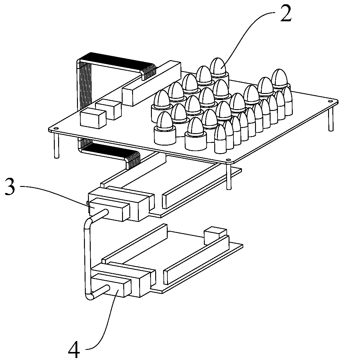
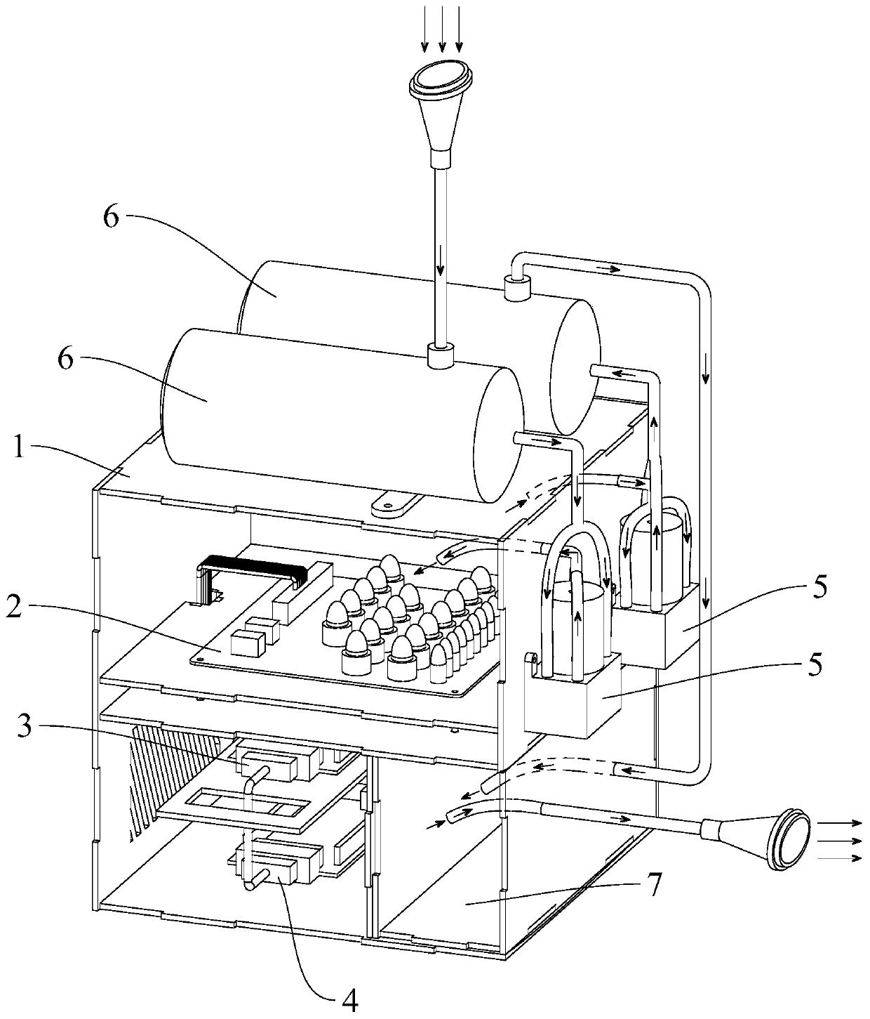
[0027] Embodiment 1 of the present invention provides a gas detection and ventilation device. The gas detection and ventilation device includes a housing 1, a detection component and a ventilation component; the detection component is arranged in the housing 1, and the detection component includes a sensor array 2, a signal conversion part 3 and a signal processing part 4, and the signal conversion part 3 is connected with the sensor respectively. The array 2 and the signal processing unit 4 are connected in communication; the ventilation assembly is arranged on the housing 1 to exchange the gas in the housing 1 , and the ventilation assembly is in communication connection with the control unit.

[0028] The gas detection and ventilation device provided by Embodiment 1 of the present invention can ensure that the gas to be detected and the detection components are sealed in the housing 1 at the same time by arranging the detection component in the housing 1, thus improving the ...

Embodiment 2

[0044] According to another aspect of the present invention, Embodiment 2 of the present invention provides a method for using a gas detection and ventilation device, which is implemented based on the gas detection and ventilation device in Embodiment 1.

[0045] The method for using the gas detection and ventilation device provided in Embodiment 2 of the present invention can ensure that the gas to be detected and the detection components are sealed in the casing 1 at the same time by using the gas detection and ventilation device in Embodiment 1, which improves the limited airtightness. The contact efficiency between the gas to be detected and the detection components in the space shortens the detection time and ensures the detection efficiency. In addition, by passing the gas to be detected into the casing 1, the passive detection in the prior art is changed into active sampling detection, which improves the active response capability of the gas detection and ventilation dev...


PUM


Abstract

The invention relates to the field of gas detection, and discloses a gas detecting and ventilating device and a using method thereof. The gas detecting and ventilating device comprises a casing, a detecting component and a ventilating component, wherein the detecting component is disposed in the casing and comprises a sensor array, a signal converting part and a signal processing part, and the signal converting part is respectively connected to the sensor array and the signal processing part; the ventilating component is disposed on the casing for exchanging gas in the casing and is communicatively coupled to a control part. The gas detecting and ventilating device provided by the invention can ensure that the gas to be detected and the detecting component are simultaneously sealed in thecasing by providing the detecting component in the casing, thereby improving the contact efficiency between the gas to be detected and the detecting component in the space of the limited closed space,shortening the detection time and ensuring the detection efficiency. In addition, the passive detection in the prior art is changed to active sampling detection, which improves the active response capability of the gas detecting and ventilating device.

Description

technical field [0001] The invention relates to the field of gas detection, in particular to a gas detection ventilation device and a method for using the same. Background technique [0002] Electronic noses have broad application prospects in universal scenarios. At present, there are many supporting detection devices and technologies for the sense of smell in the world. At present, the technology of electronic noses is mainly used to simulate the human olfactory system. Electronic noses, also known as odor scanners, are an emerging Intelligent sensory instruments generally use specific sensors and pattern recognition systems to quickly provide the overall signal of the detected sample, indicating the hidden characteristics of the sample. Electronic nose technology has a short response time and fast detection speed, unlike other instruments, such as gas chromatography sensors and high performance liquid chromatography sensors, which require complex pretreatment processes; i...

Claims


Application Information

Patent Timeline
Patent Type & Authority Applications(China)
IPC IPC(8): G01N1/24G01N35/00G01N35/10F04B39/00F04B51/00
CPCF04B39/0083F04B51/00G01N1/24G01N35/00722G01N35/10
Inventor 徐迎庆贾艳红路奇彭宇高家思
Owner TSINGHUA UNIV
Why Eureka
Try Eureka