Power battery pack, energy storage device and electric vehicle

A technology for power battery packs and single cells, which is applied in power units, electric power units, electric vehicles, etc., can solve the problem that the battery life of the power battery pack cannot be effectively improved, the utilization rate of the installation area of ​​the chassis is low, and the increase of the accommodating device Production process complexity and other issues to achieve the effect of improving battery life, achieving lightweight, and reducing weight

Active Publication Date: 2019-08-30
BYD CO LTD
View PDF6 Cites 5 Cited by
  • Summary
  • Abstract
  • Description
  • Claims
  • Application Information

AI Technical Summary

Problems solved by technology

[0004] 1. Due to the existence of beams and longitudinal beams, the volume utilization rate of the storage device is low, about 40%, and the number of single batteries that can be installed is limited, which cannot effectively improve the battery life of the power battery pack;
[0005] 2. The traditional power battery pack contains many battery modules. During the assembly process, each battery module needs to be fixed to the beam, and a large number of screws and other fasteners are required to fasten the modules. At the same time The beam or stringer has a certain weight, resulting in an increase in the weight of the containment device;
[0006] 3. Beams and longitudinal beams are arranged in the containment device, and the structure is complex, which increases the complexity of the manufacturing process of the containment device;
[0007] 4. The single battery needs to be assembled into a battery module and then placed in the storage device. The operation steps are complicated
[0008] In addition, in order to facilitate the arrangement of battery modules, the accommodating device is usually designed as a square or a rectangle, which has a low degree of matching with the shape of the chassis of the vehicle body, and has a low utilization rate of the installation area of ​​the chassis of the vehicle body, further reducing the number of cells installed on the vehicle body. The number of batteries, thereby impairing the range of the vehicle

Method used


Image

  • Power battery pack, energy storage device and electric vehicle
  • Power battery pack, energy storage device and electric vehicle
  • Power battery pack, energy storage device and electric vehicle

Examples


Embodiment approach

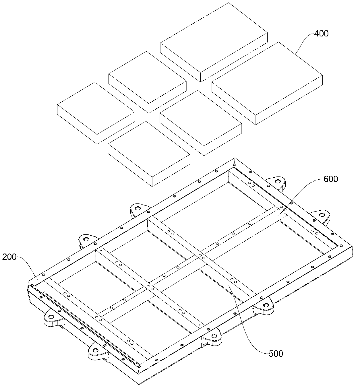
[0186] As an implementation manner, the power battery pack is arranged at the bottom of the electric vehicle, and the accommodating device 200 is fixedly connected to the chassis of the electric vehicle. Since the installation space at the chassis of the electric vehicle is large, disposing the power battery pack at the chassis of the electric vehicle can increase the number of single batteries 100 as much as possible, thereby improving the battery life of the electric vehicle. Here, there may be one or more power battery packs arranged at the bottom of the electric vehicle.

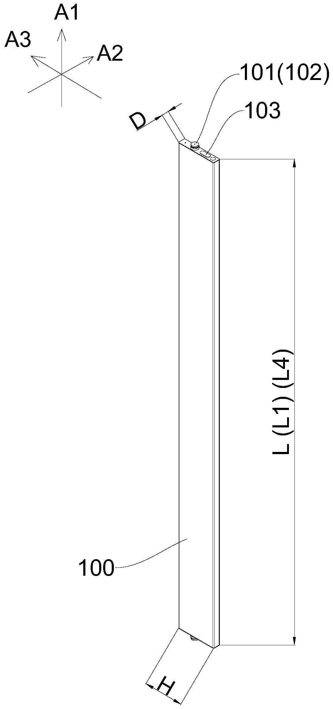
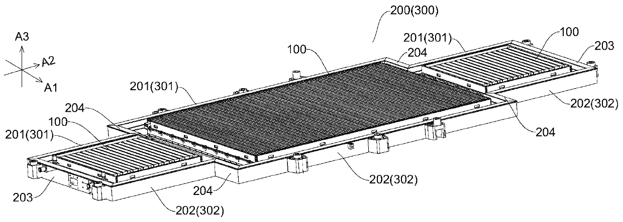
[0187] Optionally, the electric vehicle includes a power battery pack disposed at the bottom of the electric vehicle, the accommodating device 200 is fixedly connected to the chassis of the electric vehicle, and the plurality of single batteries 100 are arranged along a second direction A2 different from the first direction A1, The first direction A1 is the vehicle body width direction of the electric ve...


PUM

PropertyMeasurementUnit
lengthaaaaaaaaaa
lengthaaaaaaaaaa

Abstract

The invention relates to a power battery pack, an energy storage device and an electric vehicle. The power battery pack comprises an accommodating device and a plurality of battery single bodies arranged in the accommodating device. The accommodating device is provided with a plurality of accommodating areas. Each accommodating area is provided with a first frame and a second frame which are oppositely arranged in the first direction, and the battery single bodies arranged between the first frame and the second frame. The first frame and the second frame have different intervals along the first direction among different accommodating areas. Each battery single body comprises a first end and a second end which are opposite to each other, and the distance between the first end and the secondend of each battery single body is matched with the distance between the corresponding first frame and the corresponding second frame. Due to the fact that the battery single bodies extend between the first frame and the second frame, use of the cross beams and/or the longitudinal beams can be reduced, the space utilization rate of the accommodating device is increased, and the accommodating device is provided with the plurality of accommodating areas different in shape and size and can be matched with the structure and shape of an installation space on an electric vehicle.

Description

technical field [0001] The present disclosure relates to the technical field of power battery packs, and in particular, to a power battery pack, an energy storage device using the power battery pack, and an electric vehicle using the power battery pack. Background technique [0002] In the prior art, the power battery pack mainly includes a receiving device and a plurality of battery modules installed in the receiving device. The battery module is mainly assembled from a plurality of single cells. The beams are arranged around the base plate. In order to make the receiving device have sufficient strength and facilitate the installation of the battery module, a plurality of crossbeams and longitudinal beams are usually arranged between the side beams, and the plurality of crossbeams, longitudinal beams, side beams and the bottom plate jointly define a plurality of There are multiple accommodation spaces for the battery modules, and each battery module is arranged in a corres...

Claims


Application Information

Patent Timeline
Patent Type & Authority Applications(China)
IPC IPC(8): H01M2/10B60L50/64
CPCH01M50/20H01M50/209H01M50/249H01M50/267H01M50/367H01M10/613H01M10/625H01M10/647H01M10/6556H01M10/6567H01M50/103H01M50/131B60K1/04B60K2001/0438B60K2001/005B60Y2304/03B60Y2304/072H01M2220/20H01M50/207H01M50/233H01M50/3425H01M50/358H01M50/394B60L50/66
Inventor 孙华军鲁志佩唐江龙江文锋朱燕
Owner BYD CO LTD
Why Eureka
Try Eureka