Hybrid supporting self-balancing machine tool electric spindle structure and control method thereof
An electric spindle and self-balancing technology, which is applied in the direction of manufacturing tools, metal processing machinery parts, large fixed members, etc., can solve the problems of decreased reliability of the magnetic levitation spindle and increased complexity of the control system, etc.
- Summary
- Abstract
- Description
- Claims
- Application Information
AI Technical Summary
Problems solved by technology
Method used
Image

Examples
Embodiment 1
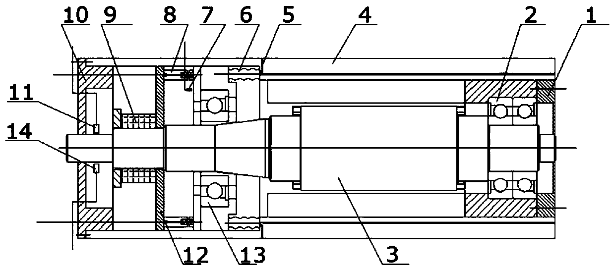
[0037] Such as Figure 1-6 Shown: a hybrid supporting self-balancing machine tool electric spindle structure, including a spindle housing 4, a first support member 2 arranged at the rear end of the spindle housing 4, and a spindle body 3 arranged in the spindle housing 4 , the second supporting member 9 arranged at the front end of the main shaft housing 4 and matched with the main shaft body 3 is arranged in the main shaft housing 4 and located at the rear end of the second supporting member 9 for automatic adjustment Auxiliary support mechanism, and a control system arranged on the main shaft housing 4 for controlling the auxiliary support mechanism;
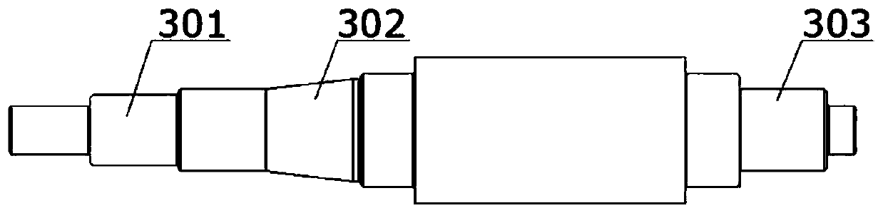
[0038] The main shaft body 4 is a multi-stage stepped shaft, at least including a tapered journal 302 matched with the auxiliary support mechanism, a rear journal 303 matched with the first support member, and a rear journal 303 matched with the first supporting member. The front end journal 301 that the two bearings match. ...
Embodiment 2
[0051] It differs from Embodiment 1 in that:
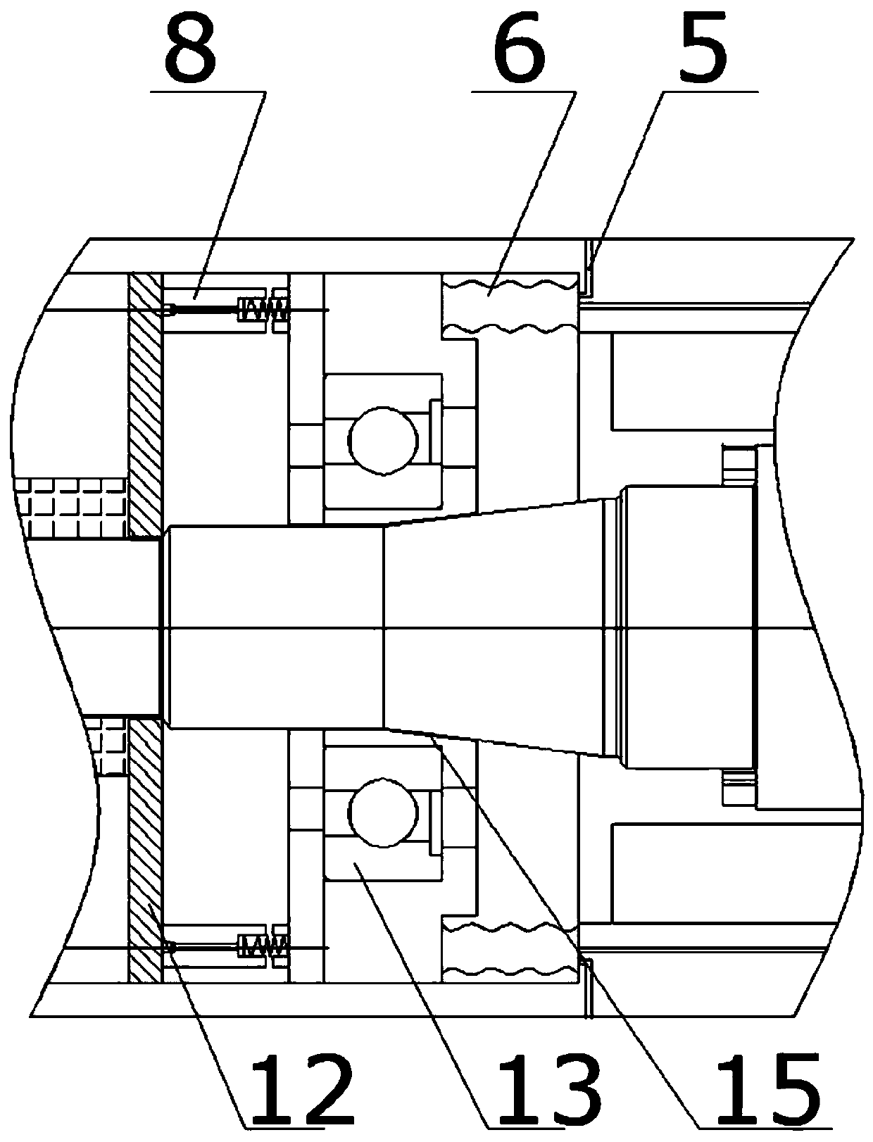
[0052] The floating supporting member 6 is an elastic rubber block with an air bag in the middle.
[0053] The elastic member 8 is an elastic rubber column.
[0054] The fixed sleeve 12 is a ceramic sleeve.
[0055] The second supporting member 9 is a permanent magnetic block magnetic suspension bearing arranged on the front journal 301 and in contact with the fixed sleeve 12 .
Embodiment 3
[0057] Such as Figure 7 As shown, the difference from Embodiment 1 is that the floating support 6 used in this embodiment is an elastic bellows, and the control system includes a reversing valve 19 communicated with the elastic bellows, and the reversing valve is connected to the elastic bellows. The speed regulating valve 20 is connected, and the speed regulating valve 20 is connected with the booster cylinder 21 to achieve a stable output pressure, and the pressure sensor 22 installed on the pipeline 5 can monitor the air pressure in the pipeline to adjust the gas source switch, and the speed sensor 23 arranged on the pipeline 5 can monitor the size of the airflow, and a check valve 26 is arranged on the pipeline to realize that the pressurized cylinder can leave the air source for short-term work, so that the air source 25 can be Perform intermittent work to reduce energy consumption, and set an overflow safety valve 24 on the pipeline between the speed sensor and the gas ...
PUM
 Abstract
Description
Claims
Application Information
 - R&D Engineer
- R&D Manager
- IP Professional
- Industry Leading Data Capabilities
- Powerful AI technology
- Patent DNA Extraction
Browse by: Latest US Patents, China's latest patents, Technical Efficacy Thesaurus, Application Domain, Technology Topic.
© 2024 PatSnap. All rights reserved.Legal|Privacy policy|Modern Slavery Act Transparency Statement|Sitemap