
High-strength welding hard industrial cutter

A welding type, high-strength technology, applied in manufacturing tools, drilling tool accessories, metal processing equipment, etc., can solve the problems of tool falling off, collapse, reducing the bonding degree of cemented carbide and tool head body, etc., to improve the tightening The effect of high strength, extended service life, and simple and convenient fixing method

Inactive Publication Date: 2019-09-06
SUZHOU MAIKAFU IND TECH CO LTD
View PDF0 Cites 0 Cited by
  • Summary
  • Abstract
  • Description
  • Claims
  • Application Information

AI Technical Summary

Problems solved by technology

[0004] The object of the present invention is to provide a high-strength welded hard industrial tool to solve the problem that the hard industrial tool proposed in the above background technology usually adopts a three-piece welding method, and only welds hard parts on both sides of the tool tip and the cutting part. Cemented carbide, such multiple welding is easy to reduce the bond between the cemented carbide and the body of the cutter head, resulting in the problem that the cutter is prone to falling off and collapsing

Method used


Image

  • High-strength welding hard industrial cutter
  • High-strength welding hard industrial cutter
  • High-strength welding hard industrial cutter

Examples


Embodiment Construction

[0020] The following will clearly and completely describe the technical solutions in the embodiments of the present invention with reference to the accompanying drawings in the embodiments of the present invention. Obviously, the described embodiments are only some, not all, embodiments of the present invention.

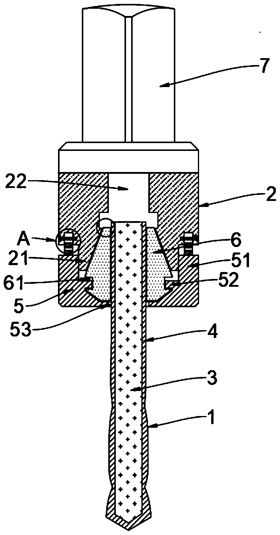
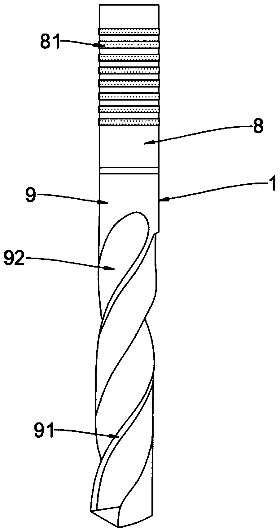
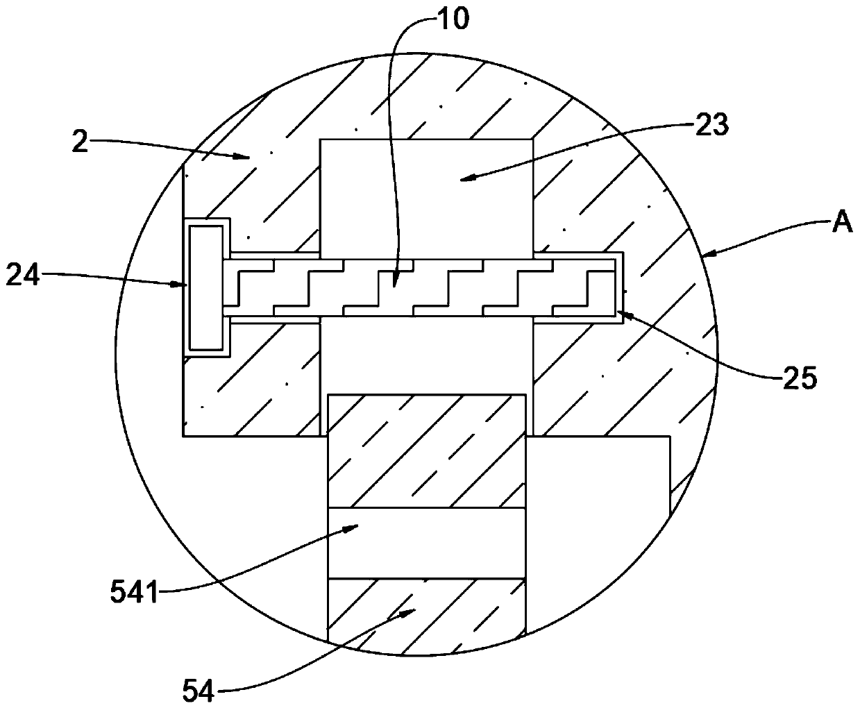
[0021] see Figure 1-4 , an embodiment provided by the present invention: a high-strength welded hard industrial tool, including a handle 2, the lower end of the handle 2 is provided with a connecting body 21, and the outside is provided with threads, and the connecting body 21 and the handle 2 One-piece structure, good integrity, not easy to break, the inside of knife handle 2 is provided with empty groove 22, and the bottom of empty groove 22 is provided with moving groove 26, and the both sides of moving groove 26 is provided with fixing groove 23, and one side of fixing groove 23 One side is provided with a T-shaped threaded hole 24, and the other side of the fix...


PUM


Abstract

The invention discloses a high-strength welding hard industrial cutter, relates to the technical field of hard industrial cutters, and solves the problems of easy fall and collapse of the cutter caused by easy reduction of the bonding degree between hard alloys and a tool bit main body due to multi-place welding of only welding the hard alloys on a tool point of the cutter and two sides of a cutting part in a three-piece welding method generally adopted by a traditional hard industrial cutter. A connecting body is arranged at the lower end of a shank; an empty groove is formed in the shank; amovable groove is formed under the empty groove; fixed grooves are arranged on the two sides of the movable groove; T-shaped thread holes are formed in one sides of the fixed grooves; second thread holes are formed in the other sides of the fixed grooves; a spring chuck is mounted in the movable groove; a locking groove is formed in the spring chuck; a limiting groove is arranged at the external under the spring chuck; a nut sleeve is mounted under the spring chuck; and a tool bit is mounted in the locking groove.

Description

technical field [0001] The invention relates to the technical field of hard industrial cutting tools, in particular to a high-strength welded hard industrial cutting tool. Background technique [0002] In the process of modern industrial processing, industrial tools are usually used to process workpieces. The quality and structure of industrial tools directly affect the quality and efficiency of produced parts. In the process of industrial processing, it is necessary to drill holes for some workpieces with high hardness. In order to ensure the smooth processing, hard industrial tools are usually used during processing, which have higher hardness, greater rigidity and longer service life, so hard industrial tools It has been widely used and developed. [0003] However, the existing hard industrial knives usually adopt a three-piece welding method, and only weld the cemented carbide on both sides of the knife tip and the cutting part of the tool. Such multiple welding is easy...

Claims


Application Information

Patent Timeline
Patent Type & Authority Applications(China)
IPC IPC(8): B23B51/00
CPCB23B51/00B23B2222/28B23B2251/02
Inventor 黄磊
Owner SUZHOU MAIKAFU IND TECH CO LTD
Learn More