Particle material contact stress visualization test loading device and using method thereof

A technology of contact stress and loading equipment, which is applied in the direction of analyzing materials, testing material strength by applying stable shear force, testing material strength by applying stable tension/pressure, etc. Problems such as heterosexuality and contact stress cannot be directly tested and observed

Active Publication Date: 2019-09-06
EAST CHINA JIAOTONG UNIVERSITY
View PDF9 Cites 3 Cited by
  • Summary
  • Abstract
  • Description
  • Claims
  • Application Information

AI Technical Summary

Problems solved by technology

[0003] At present, the deformation and strength analysis methods of granular materials are evaluated by observing the strain of granular materials, while the research on the complex stress of granular materials is only obtained through the conversion of the granular constitutive relationshi...

Method used


Image

  • Particle material contact stress visualization test loading device and using method thereof
  • Particle material contact stress visualization test loading device and using method thereof
  • Particle material contact stress visualization test loading device and using method thereof

Examples


Embodiment 1

[0059] The steps of pure shear horizontal loading mode are as follows:

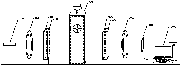
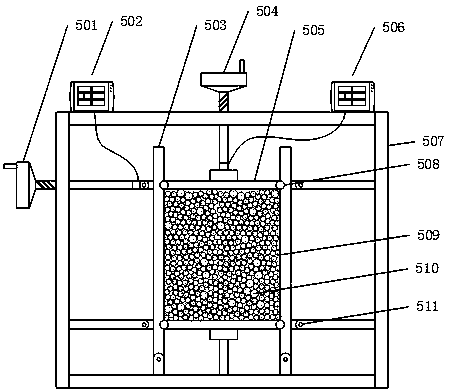
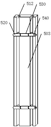
[0060] (1) Make a granular sample 510 according to the size of the sample container, put the granular sample 510 into the experimental container, and fix it on the internal support device of the loading device 500, turn the cross knob 523, and insert the slideway pin 524 into the slideway 512 In the reserved hole, the horizontal baffle 505 cannot move up and down.

[0061] (2) Press the button 544, the horizontal baffle 505 and the vertical baffle 503 can rotate, and adjust the horizontal shear screw head 501 to adjust the sample container to a vertical state, press the button 544 again to make the button pop up, At this time, the horizontal baffle 505 and the vertical baffle 503 cannot rotate, and the horizontal shear screw head 501 is fixed to keep the vertical baffle 503 from being displaced during the axial loading process.

[0062] (3) Rotate the cross knob 523 to make the card pin 524 withdraw from...

Embodiment 2

[0065] The steps for pure shear loading are as follows:

[0066] (1) Make a particle sample 510 according to the size of the sample container, put the sample into the experimental container, and fix it on the internal support device of the loading device 500, turn the cross knob 523, and insert the slideway pin 524 into the pre-set position of the slideway 512. Stay in the hole so that the horizontal baffle 505 cannot move up and down.

[0067] (2) Press the button 544, the horizontal baffle 505 and the vertical baffle 503 can rotate, and adjust the horizontal shear screw head 501 so that the lateral horizontal shear screw head 501 lightly touches the stress-displacement sensor, from the side The reading at this time is zero to the stress displacement meter 502, ensuring that the sample container is adjusted to a vertical state at this time.

[0068] (3) Start loading from the reading zero, record the image state with the photoelastic experimental equipment every certain read...


PUM


Abstract

The invention, which relates to the technical field of photoelasticity and particle mechanics, discloses a particle material contact stress visualization test loading device comprising a photo-elasticexperiment device and a loading device that work independently. The loading device includes a rectangular frame; a horizontal baffle is connected to the middle part of the upper end of the rectangular frame by a vertical axial spiral head and a vertical baffle is connected to the middle of the front side of the rectangular frame by a horizontal shearing spiral head. In addition, the invention also discloses a using method of the device. A particle sample is loaded by the loading device; the dynamic stress change of the particle sample is dynamically captured by using the photo-elastic experiment device; and then the stress change image is analyzed by a computer. According to the invention, the contact stress state of the particle material can be studied deeply by three kinds of loading modes of the loading device; the visual image displaying of the stress distribution (force chain) of the particle material can be provided by using the photo-elastic experiment device; and the image isanalyzed by using computer software to obtain the stress distribution of all positions.

Description

technical field [0001] The invention relates to the technical fields of photoelasticity and particle mechanics, in particular to a loading device for a granular material contact stress visualization test and a use method thereof. Background technique [0002] Granular material refers to small and round substances (Particle). The simplest particle shape is a sphere. Particles with a particle size of 40-500 μm and a gas-solid density difference of 1400-4000 kg / m3 are called coarse particles; particles with a particle size of 20-100 μm and a gas-solid density difference of less than 1400 kg / m3 It is called fine particle (Fine particle); the particle system composed of many particles with small particle size intervals is called particle swarm. [0003] At present, the deformation and strength analysis methods of granular materials are evaluated by observing the strain of granular materials, while the research on the complex stress of granular materials is only obtained through...

Claims


Application Information

Patent Timeline
IPC IPC(8): G01N3/02G01N3/08G01N3/24G01L5/00
CPCG01L5/00G01N3/02G01N3/08G01N3/24
Inventor 耿大新刘鑫磊胡文韬陶彪王俊廖煜祺孟成吴金亮魏日祥曹超超
Owner EAST CHINA JIAOTONG UNIVERSITY
Why Eureka
Try Eureka