Time domain signal waveform measuring method and device and digital oscilloscope

A time-domain signal and waveform measurement technology, applied in the field of signal measurement, can solve problems such as inaccurate measurement results and large errors, and achieve the effects of improving selection accuracy, accuracy, and approximation

Active Publication Date: 2019-09-06
SHENZHEN CITY SIGLENT TECH
View PDF10 Cites 6 Cited by
  • Summary
  • Abstract
  • Description
  • Claims
  • Application Information

AI Technical Summary

Problems solved by technology

[0006] The technical problem mainly solved by the present invention is how to overcome the problem of inaccurate measurement results and large errors existing when the existing digital oscilloscope measures the waveform of the digital time domain signal

Method used


Image

  • Time domain signal waveform measuring method and device and digital oscilloscope
  • Time domain signal waveform measuring method and device and digital oscilloscope
  • Time domain signal waveform measuring method and device and digital oscilloscope

Examples


Embodiment 1

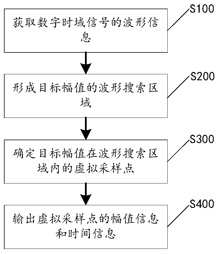
[0048] Please refer to image 3 , the present application discloses a method for measuring waveforms of time-domain signals, including steps S100-S400, which will be described respectively below.

[0049] Step S100, acquiring waveform information of the digital time-domain signal, where the waveform information includes a plurality of point sets corresponding to amplitudes, and each point set includes several sampling points with the same amplitude and different sampling numbers.

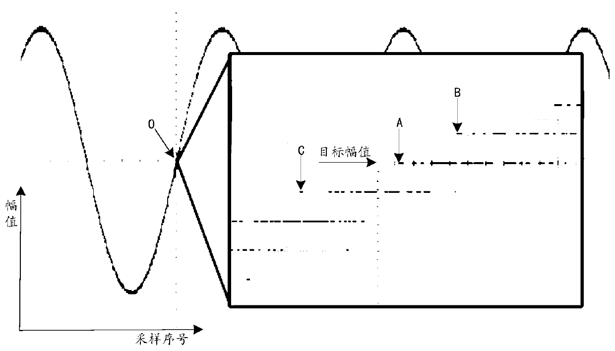
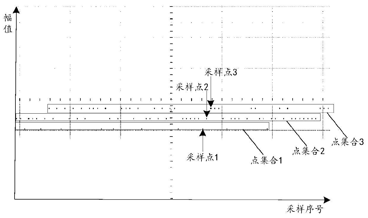
[0050] For example Figure 6 , by processing the digital waveform at point O in the digital time-domain signal, the point set corresponding to each amplitude on the vertical axis can be obtained, and each point set includes some samples with the same amplitude and different sampling numbers in discrete distribution Points, each sampling point is distributed according to the order of sampling number (or according to the order of sampling time), for details, please refer to figure 2 The set of poin...

Embodiment 2

[0076] Please refer to Figure 10 , a waveform measurement device 6 for a time-domain signal is disclosed in this embodiment, which corresponds to the waveform measurement method disclosed in Embodiment 1. The structural diagram of the waveform measurement device 6 can be specifically referred to Figure 10 , which mainly includes an acquisition unit 61 , a construction unit 62 , a calculation unit 63 , and an output unit 64 .

[0077] The acquiring unit 61 is used to acquire waveform information of the digital time-domain signal, the waveform information includes a plurality of point sets corresponding to the respective amplitudes, and each point set includes several sampling points with the same amplitude and different times. For the display form of waveform information, please refer to Figure 6 and figure 2 , which will not be repeated here.

[0078] In a specific embodiment, the waveform information of the digital time series signal is stored in a storage device or a ...

Embodiment 3

[0085] Please refer to Figure 11 , the present application also discloses a digital oscilloscope 7, which mainly includes a sampling channel 71 and the waveform measurement device 6 claimed in the second embodiment.

[0086] The sampling channel 71 is used to receive the signal under test and obtain a digital time domain signal according to the signal under test. In a specific embodiment, the sampling channel 71 includes functions such as signal amplification, filtering, analog-to-digital conversion, phase-locked loop, or digital down-conversion, and can perform high-speed sampling of analog time-domain signals to obtain digital time-domain signals with a certain sampling frequency. signal, each sampling point in the digital time-domain signal has a corresponding amplitude and sampling sequence number.

[0087] The acquisition unit 61 in the waveform measurement device 6 is connected to the sampling channel 71, and can process the digital time-domain signal according to the ...


PUM


Abstract

The invention relates to a time domain signal waveform measuring method, a measuring device and a digital oscilloscope. The waveform measuring method comprises the following steps of: acquiring waveform information of a digital time domain signal; forming a waveform search area of a target amplitude according to the waveform information; calculating to obtain an expected value of each point set inthe waveform search area, and determining a virtual sampling point of the target amplitude in the waveform search area according to the expected value; and outputting amplitude information and time information of the virtual sampling point. The waveform measuring method for the protection can reduce the influence of sampling channel noise, ADC quantization errors and insufficient sampling on thepositioning accuracy of the focus, improve the approximation degree of the focus to the real waveform, and particularly reduce the influence of ADC quantization errors and insufficient sampling rate when the virtual sampling point corresponding to the attention point do not coincide with the real sampling point. The positioning accuracy of the focus is improved to be approximate to an ideal state,and the errors of operations such as optimal sampling point positioning, time (such as period) measurement and the like can be reduced to the maximum extent.

Description

technical field [0001] The invention relates to the technical field of signal measurement, in particular to a method for measuring waveforms of time-domain signals, a measuring device, and a digital oscilloscope. Background technique [0002] The concept of time is based on the start point and end point of time, and is illustrated by the cycle in the time concept. Modern oscilloscopes usually obtain it by calculating the time interval between the "phase points" of two adjacent rising edges (or falling edges). cycle. For time-domain signals expressed in two-dimensional form, the horizontal axis usually represents time and the vertical axis represents amplitude, then the "in-phase point" needs to be determined by the amplitude in the vertical direction, for example, on the rising or falling edge The zero phase point needs to be determined by the 50% amplitude point. Therefore, whether the time measurement value of the time-domain signal waveform point corresponding to a cert...

Claims


Application Information

Patent Timeline
Patent Type & Authority Applications(China)
IPC IPC(8): G01R13/02G01R29/02
CPCG01R13/0209G01R13/0272G01R13/029G01R29/02
Inventor 郭宇昊贺锋宋民
Owner SHENZHEN CITY SIGLENT TECH
Why Eureka
Try Eureka