Latch based on magnetic skyrmion, trigger and control method

A magnetic skyrmion and control method technology, applied in static memory, digital memory information, instruments, etc., can solve the problem of the volatility of stored information in CMOS latches and flip-flops, difficult to completely solve, large static power consumption, etc. problem, to achieve the effect of simplifying circuit design, reducing occupied area, and reducing static power consumption

Active Publication Date: 2019-09-06
HUBEI UNIV +1
View PDF6 Cites 4 Cited by
  • Summary
  • Abstract
  • Description
  • Claims
  • Application Information

AI Technical Summary

Problems solved by technology

[0005] (1) Traditional CMOS latches and flip-flops are built from multiple CMOS logic gates, requiring a large number of transistors, resulting in a large area
[0006] (2) The stored information of CMOS latches and flip-flops is volatile, that is, the data is lost after the power is turned off, and the existing technology needs to keep the power on at all times, resulting in large static power consumption
[0008] The above technical problems are inherent in CMOS technology, and it is difficult to completely solve them at present

Method used


Image

  • Latch based on magnetic skyrmion, trigger and control method
  • Latch based on magnetic skyrmion, trigger and control method
  • Latch based on magnetic skyrmion, trigger and control method

Examples


example 1

[0065] The present invention is based on a magnetic skyrmion latch:

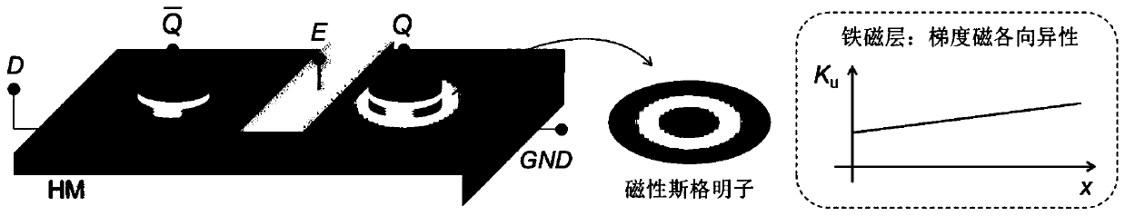
[0066] A latch based on magnetic skyrmions is characterized by a double-layer structure of a heavy metal (HM) layer and a ferromagnetic (FM) layer. A ferroelectric layer or a dielectric layer is set in the middle as the enabling end E, and a magnetic layer is placed on the right end. The tunnel junction (Magnetic TunnelJunction, MTJ) is used as the output terminal Q, and an MTJ is placed at the left end as the inverting output terminal One end of the heavy metal layer in the horizontal direction is connected to the input signal D, and the other end is grounded (GND). A magnetic skyrmion is preset in the ferromagnetic layer, and the magnetic anisotropy in the ferromagnetic layer is gradient anisotropy, that is, the magnetic anisotropy constant increases linearly along the length direction. (Such as figure 1 shown).

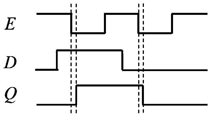
[0067] In this case, when no voltage is applied to the enable terminal E (E=0), the posit...

example 2

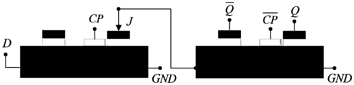
[0074] The magnetic skyrmion-based flip-flop of the present invention: two latches are cascaded to realize a master-slave D flip-flop. Connect the output of the previous latch (master) to the input of the next latch (slave). (Such as image 3 shown).

[0075] When the clock signal (CP) is at a low level, the master latch is turned on and the slave latch is turned off, realizing the data transfer from D to the output end of the master latch. When the rising edge of CP arrives, a read current pulse (J) is applied to the output of the master latch at the same time, and the voltage signal at the output of the master latch is obtained and passed to the input of the slave latch to determine the voltage of the slave latch. Output Q. (Such as Figure 4 shown).

[0076] The trigger functions based on magnetic skyrmions are shown in the table below.

[0077] Magnetic skyrmion-based trigger function table

[0078]

[0079] The present invention will be further described below i...


PUM


Abstract

The invention belongs to the technical field of digital circuits. The invention discloses a latch based on magnetic skyrmion, a trigger and a control method. The latch based on the magnetic skyrmion is of a double-layer structure composed of a heavy metal HM layer and a ferromagnetic FM layer, wherein magnetic skyrmion is preset in the ferromagnetic layer, when voltage is not applied to the enabling end E E=0, the position of the magnetic skyrmion in the ferromagnetic layer is controlled by applying voltage to the input end D, and when voltage is applied to the enabling end E E=1, the positionof the magnetic skyrmion in the ferromagnetic layer does not change along with the state of the input end D; in the invention, two latches based on the magnetic skyrmion are cascaded to form the trigger. According to the invention, the occupied area of the latch is greatly reduced, the circuit design is simplified, and the latch can be used for a time sequence logic circuit with higher density; the magnetic memory has non-volatility, so that the static power consumption of the latch and the trigger is greatly reduced.

Description

technical field [0001] The invention belongs to the technical field of digital circuits, in particular to a magnetic skyrmion-based latch and flip-flop and a control method. Background technique [0002] Currently, the closest prior art: [0003] Latches and flip-flops are important storage elements in sequential logic circuits. Traditional latches and flip-flops are built from CMOS logic gates. [0004] The problem that prior art exists is: [0005] (1) Traditional CMOS latches and flip-flops are constructed of multiple CMOS logic gates, which require the use of a large number of transistors, resulting in a relatively large area. [0006] (2) The stored information of the CMOS latch and flip-flop is volatile, that is, the data is lost after the power is turned off, and the prior art needs to keep the power on all the time, resulting in relatively large static power consumption. [0007] The difficulty of solving the above technical problems: [0008] The above-mentione...

Claims


Application Information

Patent Timeline
Patent Type & Authority Applications(China)
IPC IPC(8): G11C11/16H03K19/00
CPCG11C11/161H03K19/0008
Inventor 宋敏段威游龙罗时江顾豪爽
Owner HUBEI UNIV
Why Eureka
Try Eureka