
Heatable cloth guide roller

A fabric guide roller and heating tube technology, which is used in heating/cooling fabrics, textile processing machine accessories, fabric finishing guides/expanders, etc., can solve the problems of uneven heating of fabrics, decreased output quality, and high energy consumption. , to achieve the effect of short transfer path, small loss and good applicability

Pending Publication Date: 2019-09-10
福建省新宏港纺织科技有限公司
View PDF0 Cites 0 Cited by
  • Summary
  • Abstract
  • Description
  • Claims
  • Application Information

AI Technical Summary

Problems solved by technology

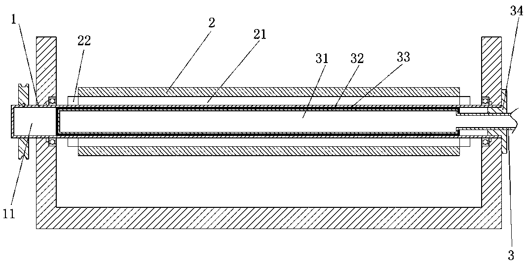
[0002] In the printing and dyeing process, during the process of unwinding, printing and dyeing, shaping, and winding of the cloth, it is necessary to display the walking path of the cloth or provide moving power through the cloth guide roller, especially in the printing and dyeing and shaping processes. Heat atmosphere to improve the effect of printing, dyeing and setting. Generally, the process environment is heated by similar heating elements such as electric heating wires located in the printing and dyeing tank or setting machine. The time of the temperature under the process is slow and the energy consumption is high; at the same time, because the existing cloth guide roller is a metal part, it is a part with a lower temperature in this kind of process with a hot atmosphere, which will lead to the heating of dyes or drying. The heat of the dry-setting cloth is absorbed by the cloth guide roller in a large amount, which consumes a lot of energy; at the same time, the temperature difference between the cloth guide roller and the process environment also makes the cloth running on it under tension easy to be heated unevenly, resulting in drop in quality

Method used


Image

  • Heatable cloth guide roller
  • Heatable cloth guide roller
  • Heatable cloth guide roller

Examples


Embodiment 1

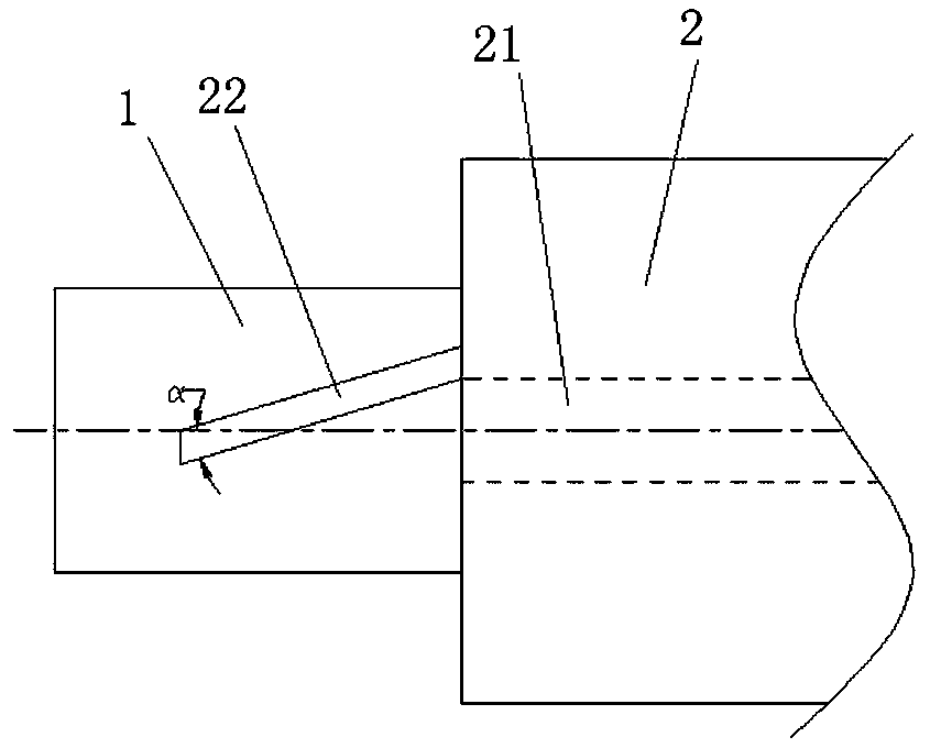
[0025] Such as figure 1 , 2 . A heating cloth guide roller shown in 3, including a longer roller shaft 1 and a shorter roller 2 coaxial inside and outside, which are integrally formed by machining, the cloth guide roller in this embodiment is used for setting in printing and dyeing The cloth is driven in the tank to move and dye in the dye. The two ends of the roller shaft 1 are rotatably installed between the two side walls of the printing and dyeing tank through bearings. The inner part of the roller shaft 1 is machined with a cavity 11 coaxial with it. Through the end of the roller shaft 1, a heating device 3 is installed in the cavity 11 from the outside to the inside of the printing and dyeing tank. Both ends of the roller shaft 1 pass through the side wall of the printing and dyeing tank. It is used to connect a chain or belt and finally connect to an external drive motor so that it can rotate under the drive of the drive motor and transmit the rotation to the fabric, a...

Embodiment 2

[0035] The technical solution described in Embodiment 2 is similar to Embodiment 1, the difference is that

[0036] Such as Figure 4 As shown, the cloth guide roller in this embodiment is applied in a drying box for drying shaped cloth, and its overall installation structure is similar to that in Embodiment 1, and it also includes an end cover 4, which is a plastic middle wearer. The shape of the rotating body passing through the roller shaft 1, which can be detachably located at both ends of the roller 2 by clamping or screwing and covering the opening of the flow groove 21, thereby reducing heat loss from the flow groove 21 and ensuring more heat concentration The drying and shaping of the cloth is realized on the surface of the roller 2.

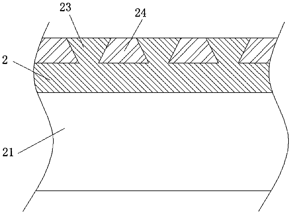
[0037] In this embodiment, the surface of the heating tube 31 protrudes a plurality of bosses along its axial direction to form a segmented heating surface 32 that contacts the inner wall of the roller shaft 1 for heat transfer, thereby...


PUM

PropertyMeasurementUnit
angleaaaaaaaaaa

Abstract

The invention provides a heatable cloth guide roller, aiming to solve problems in the prior art. The heatable cloth guide roller comprises a roller shaft and a roller body. The roller shaft and the roller body are arranged coaxially. The roller shaft is internally provided with a coaxial cavity. A heating device is penetratingly arranged in the cavity. The roller shaft rotates relative to the heating device. The outer surface of the heating device is attached to the wall surface of the cavity. The heatable cloth guide roller has the advantages that self-heating of the cloth guide roller can beeffectively realized, cloth on the surface of the cloth guide roller can be rapidly heated, time and energy consumption for heating the cloth to a required temperature in a process requiring a heat atmosphere are reduced, and accordingly, the cloth is heated evenly and stably.

Description

technical field [0001] The invention relates to the technical field of printing and dyeing equipment, in particular to a heating cloth guide roller. Background technique [0002] In the printing and dyeing process, during the process of unwinding, printing and dyeing, shaping, and winding of the cloth, it is necessary to display the walking path of the cloth or provide moving power through the cloth guide roller, especially in the printing and dyeing and shaping processes. Heat atmosphere to improve the effect of printing, dyeing and setting. Generally, the process environment is heated by similar heating elements such as electric heating wires located in the printing and dyeing tank or setting machine. The time of the temperature under the process is slow and the energy consumption is high; at the same time, because the existing cloth guide roller is a metal part, it is a part with a lower temperature in this kind of process with a hot atmosphere, which will lead to the hea...

Claims


Application Information

Patent Timeline
Patent Type & Authority Applications(China)
IPC IPC(8): D06B23/02D06C7/02D06C15/08
CPCD06B23/023D06B23/028D06C15/08D06C7/02D06C2700/10
Inventor 伍江生付艳蒋庆德
Owner 福建省新宏港纺织科技有限公司
Learn More